INSTALLATION IN EXISTING CONSTRUCTION
Use the following procedures for installation in existing construction. |
|
|
|
|
|
|
|
|
|
|
| ||||||||
Starting from farthest wall inlet location, install each inlet as described |
|
|
|
|
|
|
|
|
|
|
| ||||||||
|
|
|
|
|
|
|
|
|
|
| |||||||||
below. Working back toward power unit, connect each inlet line and |
|
|
|
|
|
|
|
|
|
|
| ||||||||
branch line into main trunk line. See page 5. Complete low voltage wiring |
|
|
|
|
|
|
| BASEBOARD | |||||||||||
as main trunk line is continued back to power unit. Mount power unit and |
|
|
|
|
|
|
|
|
|
|
| ||||||||
complete wiring. See page 8. |
|
|
|
|
|
|
|
|
|
|
| ||||||||
|
|
|
|
|
|
|
|
|
|
|
|
|
|
|
|
|
|
| TOE STRIP |
WALL INLET INSTALLATION |
|
|
|
|
|
|
|
|
|
|
| ||||||||
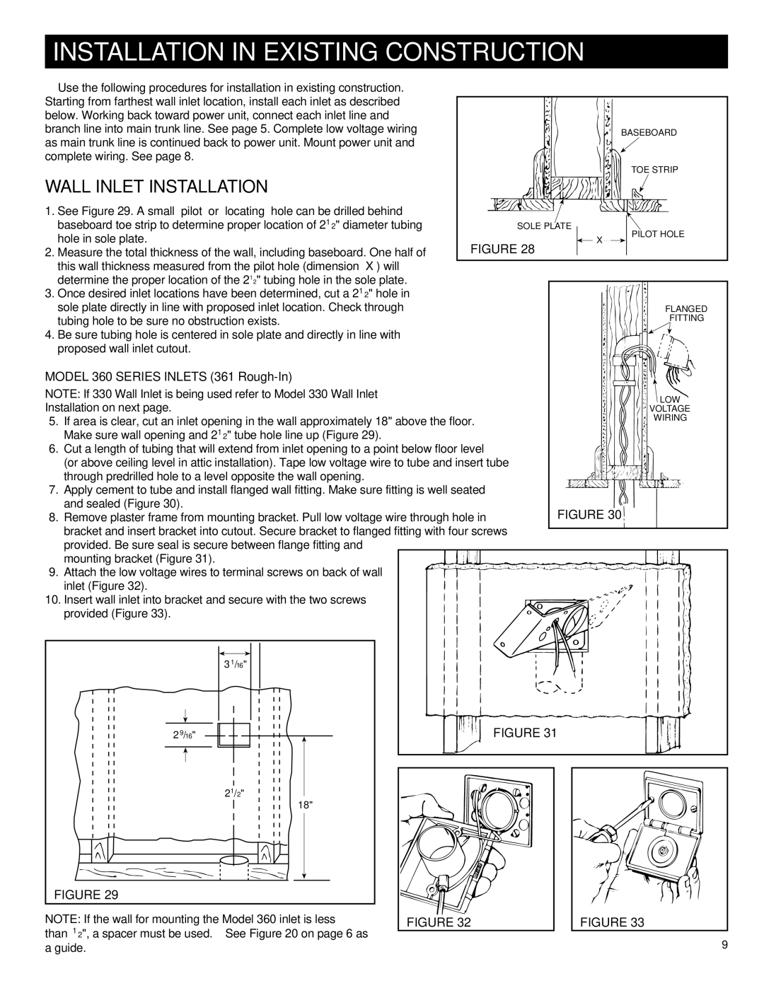
1. See Figure 29. A small ‘pilot’ or ‘locating’ hole can be drilled behind |
|
|
|
|
|
|
|
|
|
|
| ||||||||
baseboard toe strip to determine proper location of 21⁄2" diameter tubing |
| SOLE PLATE |
|
|
|
|
|
|
| PILOT HOLE | |||||||||
|
|
| |||||||||||||||||
hole in sole plate. |
|
|
|
|
|
| “X” |
|
|
| |||||||||
FIGURE 28 |
|
|
|
|
|
|
| ||||||||||||
2. Measure the total thickness of the wall, including baseboard. One half of |
|
|
|
|
|
|
|
| |||||||||||
|
| ||||||||||||||||||
this wall thickness measured from the pilot hole (dimension ‘X’) will |
|
|
|
|
|
|
|
|
|
|
| ||||||||
determine the proper location of the 21⁄2" tubing hole in the sole plate. |
|
|
|
|
|
|
|
|
|
|
| ||||||||
|
|
|
|
|
|
|
|
|
|
| |||||||||
3. Once desired inlet locations have been determined, cut a 21⁄2" hole in |
|
|
|
|
|
|
|
|
|
|
| ||||||||
sole plate directly in line with proposed inlet location. Check through |
|
|
|
|
|
|
|
|
|
| FLANGED | ||||||||
tubing hole to be sure no obstruction exists. |
|
|
|
|
|
|
|
|
|
| FITTING | ||||||||
4. Be sure tubing hole is centered in sole plate and directly in line with |
|
|
|
|
|
|
|
|
|
|
| ||||||||
proposed wall inlet cutout. |
|
|
|
|
|
|
|
|
|
|
| ||||||||
MODEL 360 SERIES INLETS (361 |
|
|
|
|
|
|
|
|
|
|
| ||||||||
NOTE: If 330 Wall Inlet is being used refer to Model 330 Wall Inlet |
|
|
|
|
|
|
|
|
|
| LOW | ||||||||
Installation on next page. |
|
|
|
|
|
|
|
|
|
| |||||||||
|
|
|
|
|
|
|
|
|
| VOLTAGE | |||||||||
5. If area is clear, cut an inlet opening in the wall approximately 18" above the floor. |
|
|
|
|
|
|
|
|
| WIRING | |||||||||
Make sure wall opening and 21⁄2" tube hole line up (Figure 29). |
|
|
|
|
|
|
|
|
|
|
| ||||||||
6. Cut a length of tubing that will extend from inlet opening to a point below floor level |
|
|
|
|
|
|
|
|
|
| |||||||||
(or above ceiling level in attic installation). Tape low voltage wire to tube and insert tube |
|
|
|
|
|
|
|
|
|
| |||||||||
through predrilled hole to a level opposite the wall opening. |
|
|
|
|
|
|
|
|
|
|
| ||||||||
7. Apply cement to tube and install flanged wall fitting. Make sure fitting is well seated |
|
|
|
|
|
|
|
|
|
| |||||||||
and sealed (Figure 30). |
|
| FIGURE 30 | ||||||||||||||||
8. Remove plaster frame from mounting bracket. Pull low voltage wire through hole in |
| ||||||||||||||||||
bracket and insert bracket into cutout. Secure bracket to flanged fitting with four screws |
|
|
|
|
|
|
|
|
|
| |||||||||
|
|
|
|
|
|
|
|
|
| ||||||||||
provided. Be sure seal is secure between flange fitting and |
|
|
|
|
|
|
|
|
|
|
|
| |||||||
mounting bracket (Figure 31). |
|
|
|
|
|
|
|
|
|
|
| ||||||||
9. Attach the low voltage wires to terminal screws on back of wall |
|
|
|
|
|
|
|
|
|
|
| ||||||||
inlet (Figure 32). |
|
|
|
|
|
|
|
|
|
|
| ||||||||
10. Insert wall inlet into bracket and secure with the two screws |
|
|
|
|
|
|
|
|
|
|
| ||||||||
provided (Figure 33). |
|
|
|
|
|
|
|
|
|
|
| ||||||||
|
|
|
|
|
|
|
|
|
|
|
|
|
|
|
|
|
|
| |
|
|
|
|
|
|
|
|
|
|
|
|
|
|
|
|
|
|
|
|
|
|
|
|
|
|
|
|
|
|
|
|
|
|
|
|
|
|
|
|
|
| 3 1/16" |
|
|
|
|
|
|
|
|
|
|
|
|
|
|
| ||
|
|
|
|
|
|
|
|
|
|
|
|
|
|
|
|
|
|
|
|
|
|
|
|
|
|
|
|
|
|
|
|
|
|
|
|
|
|
|
|
|
|
|
|
|
|
|
|
|
|
|
|
|
|
|
|
|
|
|
|
|
|
|
|
|
|
|
|
|
|
|
|
|
|
|
|
|
|
|
|
2 9/16" | FIGURE 31 |
21/2" |
|
|
18" |
|
|
FIGURE 29 |
|
|
NOTE: If the wall for mounting the Model 360 inlet is less | FIGURE 32 | FIGURE 33 |
than 1⁄2", a spacer must be used. See Figure 20 on page 6 as |
| 9 |
a guide. |
|