INSTALLATION IN NEW CONSTRUCTION (continued)
INSTALLING THE TUBING
Use the following installation guidelines when installing tubing.
1.Start tubing installation at farthest inlet and work toward the power unit.
2.Tubing run to the power unit should be as straight as possible.
3.When assembling sections with elbows and tees, make sure the curve in the fitting is aligned so that the air flows toward the power unit.
4.Branch lines should always join the trunk line from above or from the same level. Never join a branch line from an angle below the trunk line.
5.Refer to Figure 28 on page 8. Run low voltage wiring (Model
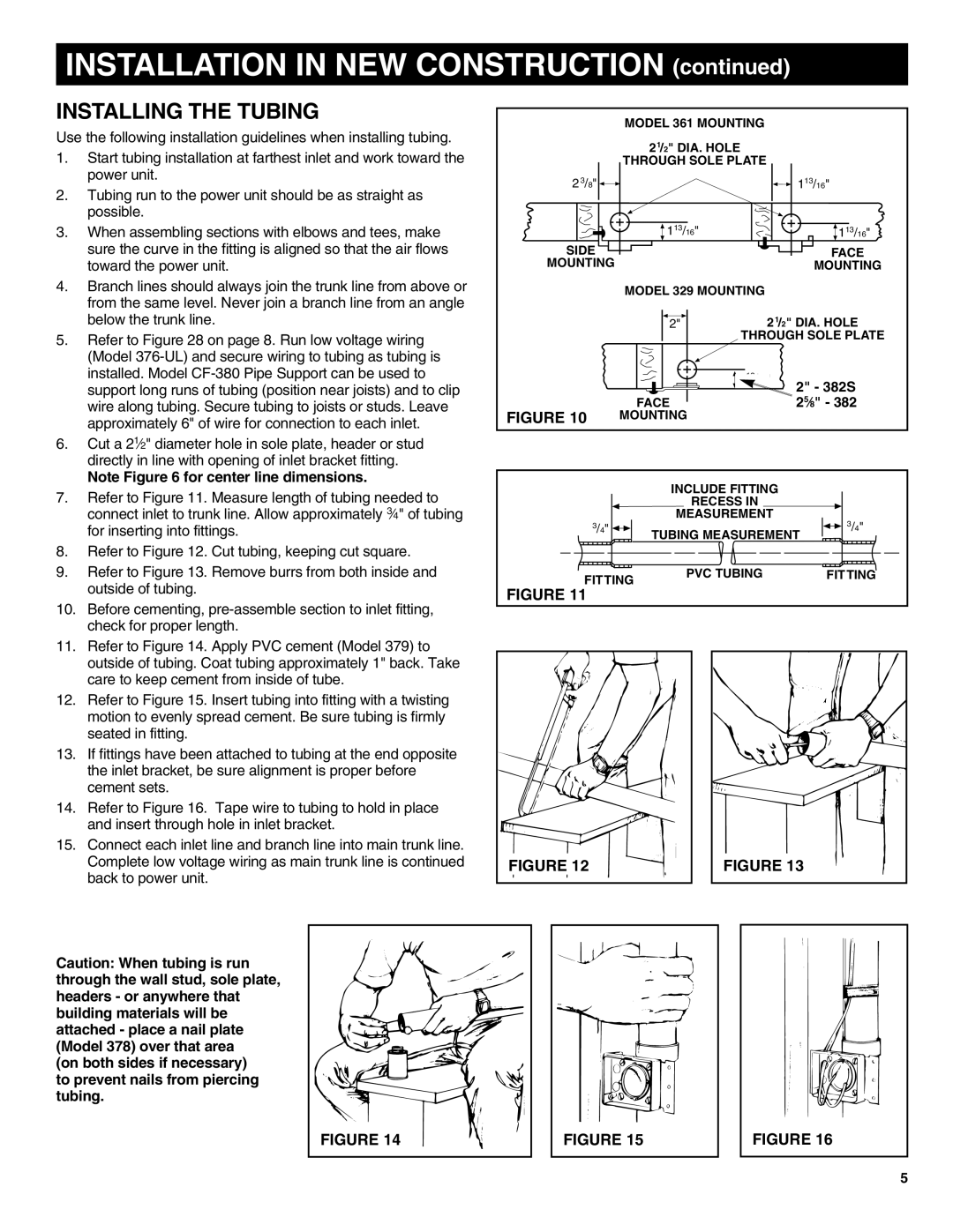
6.Cut a 21⁄2" diameter hole in sole plate, header or stud directly in line with opening of inlet bracket fitting.
Note Figure 6 for center line dimensions.
7.Refer to Figure 11. Measure length of tubing needed to connect inlet to trunk line. Allow approximately 3⁄4" of tubing for inserting into fittings.
8.Refer to Figure 12. Cut tubing, keeping cut square.
9.Refer to Figure 13. Remove burrs from both inside and outside of tubing.
10.Before cementing,
| MODEL 361 MOUNTING |
|
| 21/2" DIA. HOLE |
|
| THROUGH SOLE PLATE |
|
2 3/8" |
| 113/16" |
| 113/16" | 113/16" |
SIDE |
| FACE |
MOUNTING |
| MOUNTING |
| MODEL 329 MOUNTING |
|
| 2" | 21/2" DIA. HOLE |
| THROUGH SOLE PLATE | |
|
| 2" - 382S |
| FACE | 25⁄8" - 382 |
FIGURE 10 | MOUNTING |
|
| INCLUDE FITTING |
|
| RECESS IN |
|
| MEASUREMENT | 3/4" |
3/4" | TUBING MEASUREMENT | |
|
| |
FITTING | PVC TUBING | FITTING |
|
| |
FIGURE 11 |
|
|
11.Refer to Figure 14. Apply PVC cement (Model 379) to outside of tubing. Coat tubing approximately 1" back. Take care to keep cement from inside of tube.
12.Refer to Figure 15. Insert tubing into fitting with a twisting motion to evenly spread cement. Be sure tubing is firmly seated in fitting.
13.If fittings have been attached to tubing at the end opposite the inlet bracket, be sure alignment is proper before cement sets.
14.Refer to Figure 16. Tape wire to tubing to hold in place and insert through hole in inlet bracket.
15.Connect each inlet line and branch line into main trunk line. Complete low voltage wiring as main trunk line is continued back to power unit.
FIGURE 12 |
FIGURE 13 |
Caution: When tubing is run through the wall stud, sole plate, headers - or anywhere that building materials will be attached - place a nail plate (Model 378) over that area
(on both sides if necessary) to prevent nails from piercing tubing.
FIGURE 14 |
FIGURE 15
FIGURE 16
5