Hardware Setup
IEEE1394 Connector: J1394_1 (optional)
This connector allows you to connect the IEEE1394 device via an optional IEEE1394 bracket.
Pin Definition
2
1
|
|
|
| PIN | SIGNAL | PIN | SIGNAL |
|
|
| 10 | 1 | TPA+ | 2 | TPA- |
|
|
| 3 | Ground | 4 | Ground | |
|
|
| 9 | ||||
|
|
|
|
|
|
| |
|
|
|
| 5 | TPB+ | 6 | TPB- |
|
|
|
| ||||
J1394_1 |
| ||||||
| 7 | Cable power | 8 | Cable power | |||
|
|
|
| 9 | Key(no pin) | 10 | Ground |
IEEE1394 Bracket (optional)
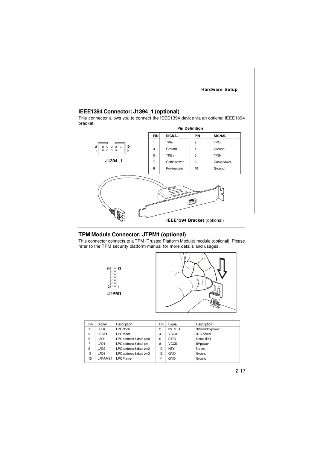
TPM Module Connector: JTPM1 (optional)
This connector connects to a TPM (Trusted Platform Module) module (optional). Please refer to the TPM security platform manual for more details and usages.
14 13
2 1
JTPM1
Pin | Signal | Description | Pin | Signal | Description |
1 | LCLK | LPCclock | 2 | 3V_STB | 3Vstandbypower |
3 | LRST# | LPC reset | 4 | VCC3 | 3.3Vpower |
5 | LAD0 | LPC address & data pin0 | 6 | SIRQ | Serial IRQ |
7 | LAD1 | LPC address & data pin1 | 8 | VCC5 | 5Vpower |
9 | LAD2 | LPC address & data pin2 | 10 | KEY | No pin |
11 | LAD3 | LPC address & data pin3 | 12 | GND | Ground |
13 | LFRAME# | LPCFrame | 14 | GND | Ground |
|
|
|
|
|
|