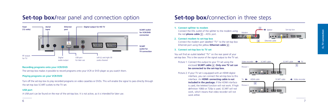
Set-top box/rear panel and connection option
Feed |
| Aerial | Ethernet |
| Digital output for HD TV | ||
|
| ||||||
(12 volts) |
| input | port |
|
|
| SCART outlet |
|
|
|
|
|
|
| for VCR/DVD |
|
|
|
|
|
|
| |
|
|
|
|
|
|
| connection |
Set-top box/connection in three steps
1. Connect splitter to modem | 3 |
|
|
| |
Connect the DSL outlet of the splitter to the modem using | Splitter |
|
|
| |
Modem |
|
|
|
| |
the red phone cable 3 – ADSL port. |
|
|
|
| |
POWER |
|
|
|
| |
|
|
|
| ||
|
|
|
|
|
|
connection
SCART outlet for TV connection
RF output |
|
|
|
|
|
|
|
| Digital | USB port | Left (L) and right (R) | ||||
for TV |
| ||||||
| audio output | for later use | audio channel | ||||
|
| ||||||
2. Connect modem to | ON/OFF |
Connect the modem port labelled “TV” to the | |
Ethernet port using the yellow Ethernet cable 4 . |
|
3. Connect set-top box to TV set
You will find an outlet labelled “TV” on the rear panel of your
Picture 1: Connect this output to your TV set using the
RESET | @2 | TV LANTV | @1 | DSL |
4Ethernet cable
Video recorder | SCART cable | SCART cable | TV |
O2 TV
Recording programs onto your VCR/DVD
enclosed SCART cable 4 . Only one TV set can
be connected to the
Picture 1
5
The
Playing programs on your VCR/DVD
Turn off the
USB port
A USB port can be found on the rear of the
Picture 2: If your TV set is equipped with an HDMI digital interface, you can connect the
TV | HDMI cable | SCART cable | Video recorder |
6
Picture 2
6 | 7 |