4.4 A/D Conversion
An A/D conversion can be initiated three different ways: software command, internal programmable interval timer or external trigger. At the end of the A/D conversion, it is possible to transfer the data by polling a status register and reading the data when ready or by generating a hardware interrupt and an interrupt service routine. All modes are selected by a control register on the
Below are key points for successfully collecting A/D data:
zA/D data register, BASE+30h, stores the A/D conversion data.
zA/D data conversion ready register, BASE +10h. Check if A/D data is ready.
zA/D gain control register, BASE+14h, select gain.
zA/D multiplexer control register, BASE+10h, select analog input channel.
zA/D mode control register, BASE+0Ch, select trigger type and transfer type.
zA/D software trigger control register, BASE+1Ch.
zJP1 select
z3 Triggers: Software, Pacer, and External trigger.
z2 Transfer Modes: Polling and Interrupt.
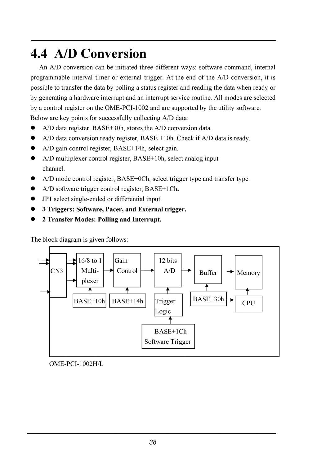
The block diagram is given follows:
| 16/8 to 1 | Gain | 12 bits |
|
|
CN3 | Multi- | Control | A/D | Buffer | Memory |
| plexer |
|
|
|
|
| BASE+10h | BASE+14h | Trigger | BASE+30h | CPU |
|
|
| Logic |
|
|
|
|
| BASE+1Ch |
|
|
|
|
| Software Trigger |
|
|
|
|
|
| ||
38