For
[Bit1,Bit0] | [0 0] | [0 1] | [1 0] | [1 1] |
Gain | 1 | 10 | 100 | 1000 |
3.These registers are set to 0 after
3.2.2.8 The General Control Register
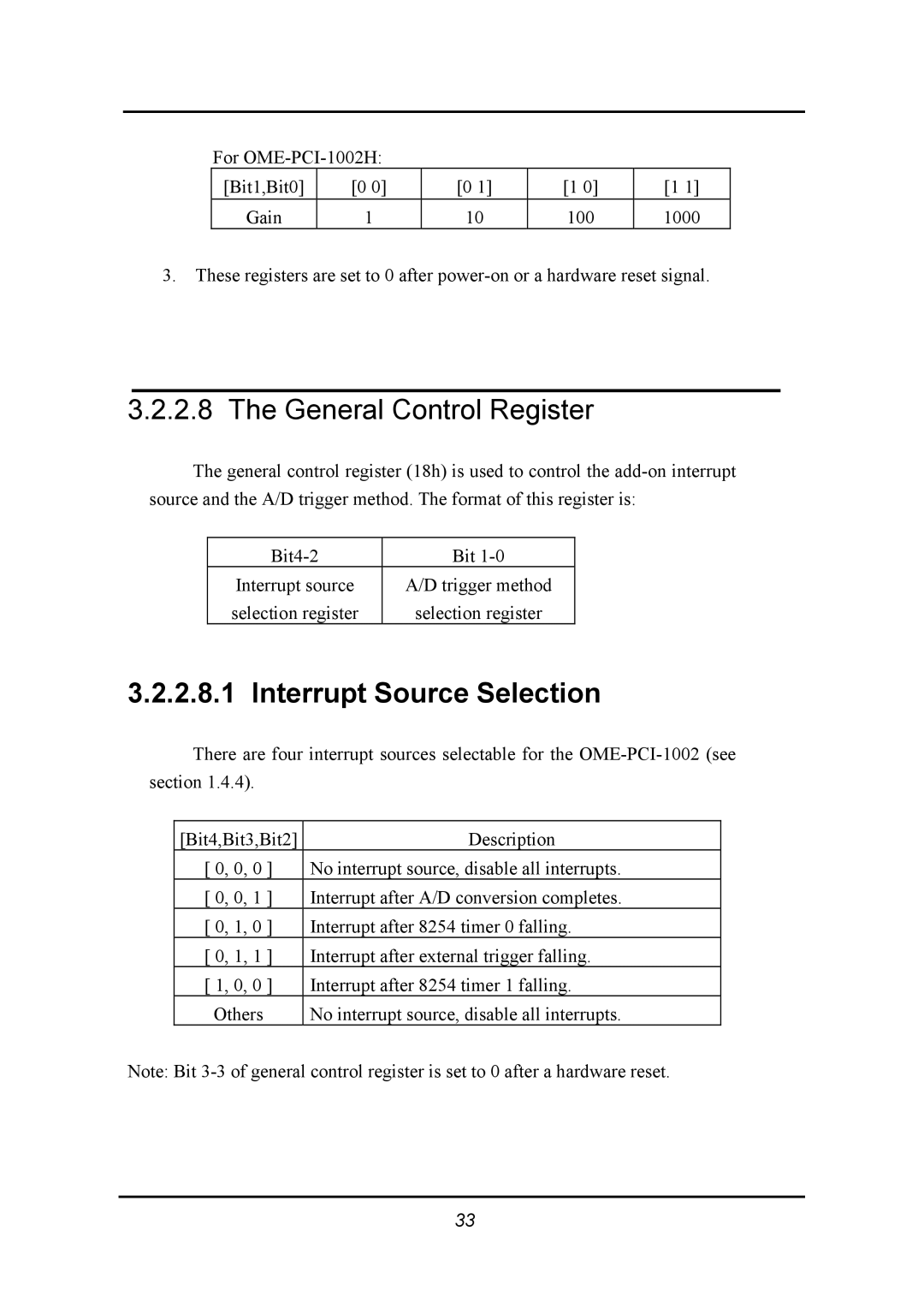
The general control register (18h) is used to control the
Bit | |
Interrupt source | A/D trigger method |
selection register | selection register |
3.2.2.8.1 Interrupt Source Selection
There are four interrupt sources selectable for the
[Bit4,Bit3,Bit2] | Description |
[ 0, 0, 0 ] | No interrupt source, disable all interrupts. |
[ 0, 0, 1 ] | Interrupt after A/D conversion completes. |
[ 0, 1, 0 ] | Interrupt after 8254 timer 0 falling. |
[ 0, 1, 1 ] | Interrupt after external trigger falling. |
[ 1, 0, 0 ] | Interrupt after 8254 timer 1 falling. |
Others | No interrupt source, disable all interrupts. |
Note: Bit
33