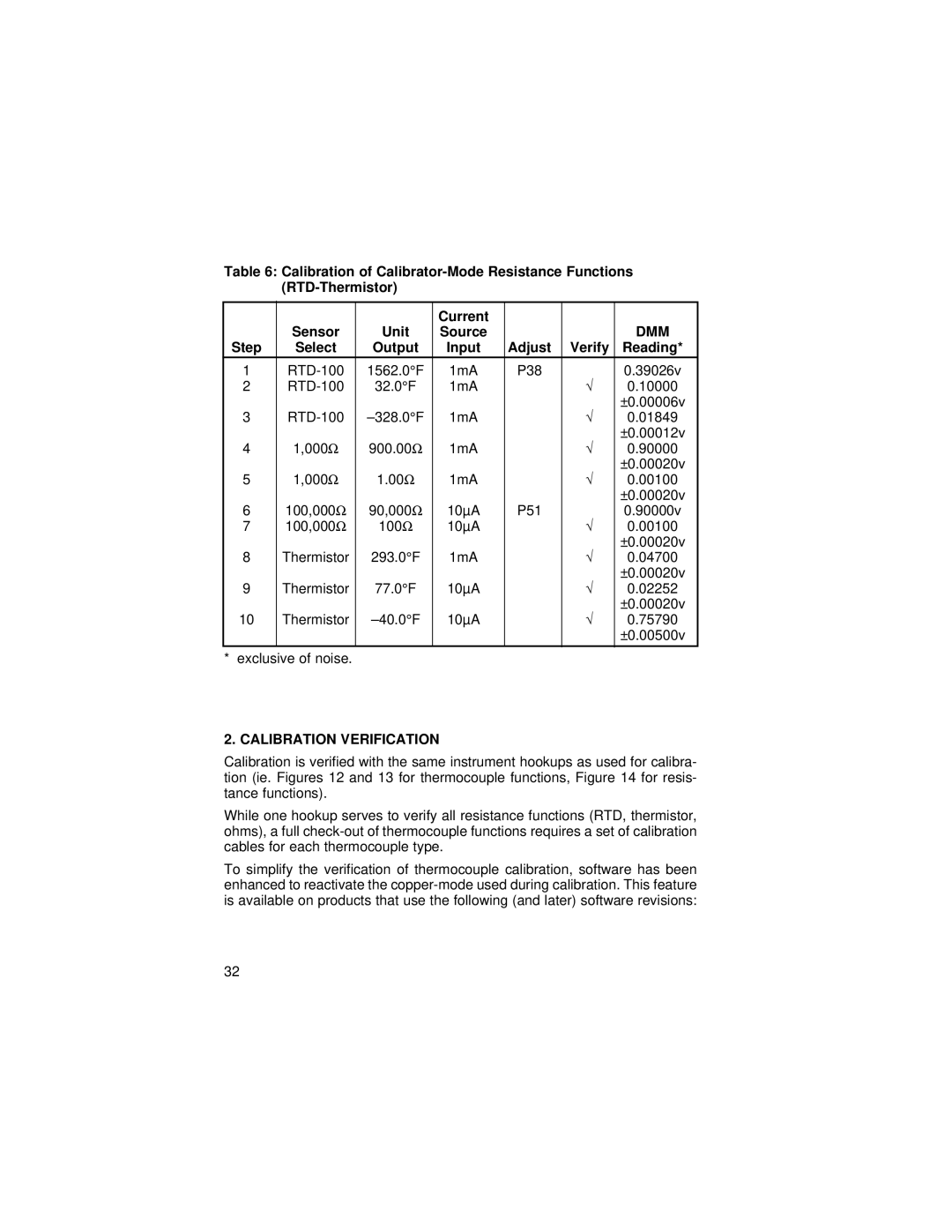
Table 6: Calibration of
|
|
| Current |
|
|
|
| Sensor | Unit | Source |
|
| DMM |
Step | Select | Output | Input | Adjust | Verify | Reading* |
1 | 1562.0°F | 1mA | P38 | √ | 0.39026v | |
2 | 32.0°F | 1mA |
| 0.10000 | ||
|
|
|
|
| √ | ±0.00006v |
3 | 1mA |
| 0.01849 | |||
| 1,000Ω | 900.00Ω |
|
| √ | ±0.00012v |
4 | 1mA |
| 0.90000 | |||
| 1,000Ω | 1.00Ω |
|
| √ | ±0.00020v |
5 | 1mA |
| 0.00100 | |||
| 100,000Ω | 90,000Ω |
|
|
| ±0.00020v |
6 | 10µA | P51 |
| 0.90000v | ||
7 | 100,000Ω | 100Ω | 10µA |
| √ | 0.00100 |
|
|
|
|
| √ | ±0.00020v |
8 | Thermistor | 293.0°F | 1mA |
| 0.04700 | |
|
|
|
|
| √ | ±0.00020v |
9 | Thermistor | 77.0°F | 10µA |
| 0.02252 | |
|
|
|
|
| √ | ±0.00020v |
10 | Thermistor | 10µA |
| 0.75790 | ||
|
|
|
|
|
| ±0.00500v |
|
|
|
|
|
|
|
* exclusive of noise. |
|
|
|
|
| |
2. CALIBRATION VERIFICATION
Calibration is verified with the same instrument hookups as used for calibra- tion (ie. Figures 12 and 13 for thermocouple functions, Figure 14 for resis- tance functions).
While one hookup serves to verify all resistance functions (RTD, thermistor, ohms), a full
To simplify the verification of thermocouple calibration, software has been enhanced to reactivate the
32