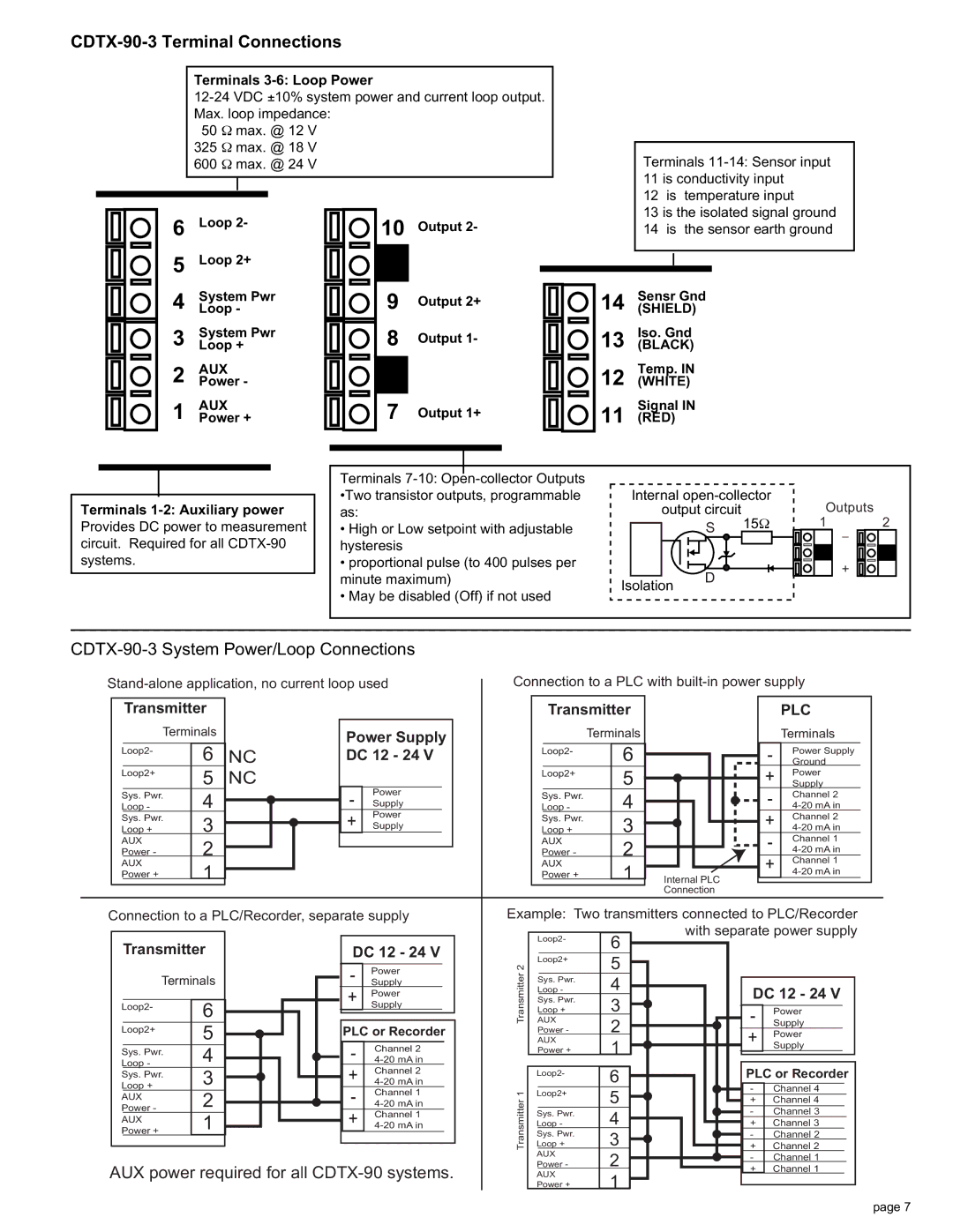
CDTX-90-3 Terminal Connections
Terminals 3-6: Loop Power
50 Ω max. @ 12 V
325 Ω max. @ 18 V
600 Ω max. @ 24 V
6 Loop 2- | 10 Output 2- |
5Loop 2+
4 | System Pwr | 9 | Output 2+ | |
Loop - |
| |||
3 | System Pwr | 8 | Output 1- | |
Loop + | ||||
2 | PowerAUX | - |
|
|
|
| |||
1 | PowerAUX | + | 7 | Output 1+ |
Terminals
12is temperature input
13is the isolated signal ground
14is the sensor earth ground
14 Sensr Gnd (SHIELD)
Iso. Gnd
13 (BLACK)
Temp. IN
12 (WHITE)
Signal IN
11 (RED)
Terminals
Provides DC power to measurement circuit. Required for all
Terminals
•High or Low setpoint with adjustable hysteresis
•proportional pulse (to 400 pulses per minute maximum)
•May be disabled (Off) if not used
Internal | Outputs |
| ||
output circuit |
|
| ||
S | 15Ω | 1 | _ | 2 |
|
|
| ||
| D | + |
Isolation |
| |
|
|
CDTX-90-3 System Power/Loop Connections
Connection to a PLC with
Transmitter
Terminals
|
|
|
Loop2- | 6 | |
| ||
|
|
|
Loop2+ | 5 | |
|
| |
Sys. Pwr. | 4 | |
Loop - | ||
Sys. Pwr. | 3 | |
Loop + | ||
AUX | 2 | |
Power - | ||
AUX | 1 | |
| Power + | |
NC NC
Power Supply DC 12 - 24 V
-PowerSupply + PowerSupply
Transmitter
Terminals
|
|
|
Loop2- | 6 | |
| ||
|
|
|
Loop2+ | 5 | |
|
| |
Sys. Pwr. | 4 | |
Loop - | ||
Sys. Pwr. | 3 | |
Loop + | ||
AUX | 2 | |
Power - | ||
AUX | 1 | |
| Power + | |
| PLC |
| Terminals |
- | Power Supply |
Ground | |
+ | SupplyPower |
- | Channel 2 |
+ | Channel 2 |
- | Channel 1 |
| |
+ | Channel 1 |
Internal PLC | |
| |
Connection |
|
Connection to a PLC/Recorder, separate supply
Example: Two transmitters connected to PLC/Recorder with separate power supply
Transmitter
Terminals
Loop2- | 6 | |
Loop2+ | 5 | |
| ||
Sys. Pwr. | 4 | |
| ||
Loop - | 3 | |
Sys. Pwr. | ||
Loop + | 2 | |
AUX | ||
Power - | 1 | |
AUX | ||
| ||
Power + |
|
DC 12 - 24 V
- | SupplyPower |
+ | Power |
| Supply |
PLC or Recorder
- | Channel 2 |
+ | Channel 2 |
- | Channel 1 |
+ | Channel 1 |
| Loop2- | 6 |
|
|
|
|
|
|
|
|
|
|
|
| |
|
|
|
|
|
|
|
|
|
|
|
|
|
|
| |
2 | Loop2+ | 5 |
|
|
|
|
|
|
|
|
|
|
|
| |
|
|
|
|
|
|
|
|
|
|
|
|
|
| ||
Transmitter |
|
|
|
|
|
|
|
|
|
|
|
|
|
|
|
Sys. Pwr. | 4 |
|
|
|
|
|
|
|
|
|
|
|
| ||
|
|
|
|
|
|
|
|
|
|
|
| ||||
Loop - |
|
|
|
|
|
|
|
| DC 12 - 24 V | ||||||
|
|
|
|
|
|
|
|
|
|
| |||||
Sys. Pwr. | 3 |
|
|
|
|
|
|
|
| ||||||
| Loop + |
|
|
|
|
|
|
|
|
|
|
|
| ||
|
|
|
|
|
|
|
| - | Power | ||||||
AUX |
|
|
|
|
|
|
|
|
| ||||||
2 |
|
|
|
|
|
|
|
| Supply | ||||||
| Power - |
|
|
|
|
|
|
|
|
|
|
|
| ||
| + | Power | |||||||||||||
|
|
|
|
|
|
|
|
|
|
|
| ||||
| AUX | 1 |
|
|
|
|
|
|
|
| |||||
|
|
|
|
|
|
|
|
| Supply | ||||||
| Power + |
|
|
|
|
|
|
|
| ||||||
|
|
|
|
|
|
|
|
|
|
|
|
| |||
|
|
|
|
|
|
|
|
|
|
|
|
|
|
|
|
|
|
|
|
|
|
|
|
|
|
|
| PLC or Recorder | |||
| Loop2- | 6 |
|
|
|
|
|
|
|
| |||||
|
|
|
|
|
|
|
|
|
|
| |||||
1 |
|
|
|
|
|
|
|
|
|
|
| - | Channel 4 |
|
|
Loop2+ | 5 |
|
|
|
|
|
|
|
| ||||||
Transmitter |
|
|
|
|
|
|
|
|
|
| + | Channel 4 |
| ||
|
|
|
|
|
|
|
|
|
| ||||||
|
|
|
|
|
|
|
|
|
|
| - | Channel 3 |
| ||
Sys. Pwr. | 4 |
|
|
|
|
|
|
|
|
| |||||
|
|
|
|
|
|
|
|
| |||||||
Loop - |
|
|
|
|
|
|
|
| + | Channel 3 | |||||
|
|
|
|
|
|
|
|
|
|
|
|
|
|
| |
Sys. Pwr. | 3 |
|
|
|
|
|
|
|
| - | Channel 2 |
| |||
|
|
|
|
|
|
|
| ||||||||
| Loop + |
|
|
|
|
|
|
|
| + | Channel 2 |
| |||
|
|
|
|
|
|
|
|
| |||||||
AUX |
|
|
|
|
|
|
|
|
| ||||||
| 2 |
|
|
|
|
|
|
|
| - | Channel 1 | ||||
| Power - |
|
|
|
|
|
|
|
| ||||||
|
|
|
|
|
|
|
|
|
|
|
|
| |||
AUX power required for all CDTX-90 systems.
|
|
|
|
| + | Channel 1 |
|
AUX | 1 |
|
|
|
| ||
|
|
|
|
|
| ||
Power + |
|
|
|
|
|
| |
|
|
|
page 7