3. Electrical Connections
Sensor Selection
Select the sensor with a range closest to your process minimum and maximum values.
•
• | 1 to 1000 ∝S | |
• | 10 to 10,000 ∝S |
•
•
Wiring Tips:
•Do not route sensor cable in conduit containing AC power wiring. Electrical noise may interfere with sensor signal.
•Routing sensor cable in grounded metal conduit will help prevent electrical noise and mechanical damage.
•Seal cable entry points to prevent moisture damage.
•Only one wire should be inserted into a terminal. Splice double wires outside the terminal.
•Sensor cable may not be extended over 100 ft.
Ultra- |
|
|
|
|
|
|
|
|
|
|
| |||||
| Pure | Pure | Rinse |
|
|
| ||||||||||
|
|
|
|
|
|
|
| |||||||||
Models |
|
|
|
|
|
|
|
|
|
|
|
|
|
| ||
|
|
|
|
|
|
|
|
|
|
|
| |||||
|
|
|
|
|
|
|
|
|
|
|
|
| ||||
Sensor |
|
|
|
|
|
|
|
|
|
|
|
|
|
|
|
|
|
|
|
|
|
|
|
|
| ||||||||
|
|
|
|
|
|
|
|
| ||||||||
|
|
|
|
|
|
|
|
|
|
|
|
|
|
|
| |
0.055 | 1 | 10 | 100 | 200 |
|
| 1,000 | 10,000 | 200,000 | 400,000 | ||||||
(18 MΩ) |
|
|
|
|
|
| (10 kΩ) |
|
|
|
| |||||
Conductivity Range (µS)
Conductivity/Resistivity | ≤ 100 ft. (30 m) |
25.0°C | |
62.50 uS/cm |
|
ENTER |
|
Caution: Failure to fully open terminal jaws before removing wire may permanently damage instrument.
Wiring Procedure
1. Remove 0.5 - 0.625 in.
2.Press the orange terminal lever downward with a small screwdriver to open terminal jaws.
3.Insert exposed
4.Release orange terminal lever to secure wire in place. Gently pull on each wire to ensure a good connection.
Wiring Removal Procedure
1.Press the orange terminal lever downward with a small screwdriver to open terminal jaws.
2.When fully open, remove wire from terminal.
2
1
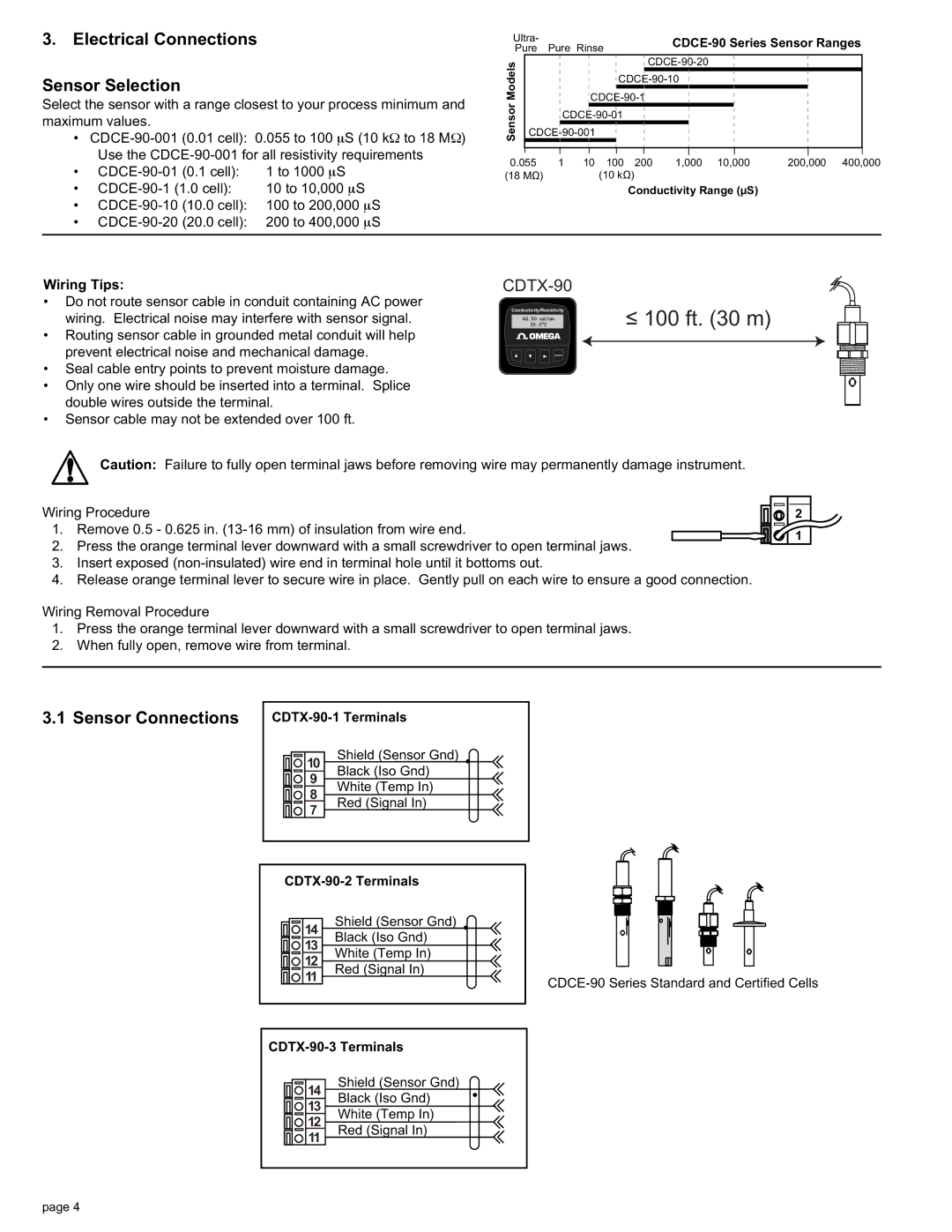
3.1 Sensor Connections
10 | Shield (Sensor Gnd) | |
Black (Iso Gnd) | ||
9 | White (Temp In) | |
8 | ||
Red (Signal In) | ||
7 | ||
| ||
| ||
14 | Shield (Sensor Gnd) |
Black (Iso Gnd) | |
13 | White (Temp In) |
12 | |
11 | Red (Signal In) |
|
14 | Shield (Sensor Gnd) |
Black (Iso Gnd) | |
13 | White (Temp In) |
12 | |
11 | Red (Signal In) |
page 4