WIRING CONNECTIONS
↑ | - ↑ | ≤ 1 V |
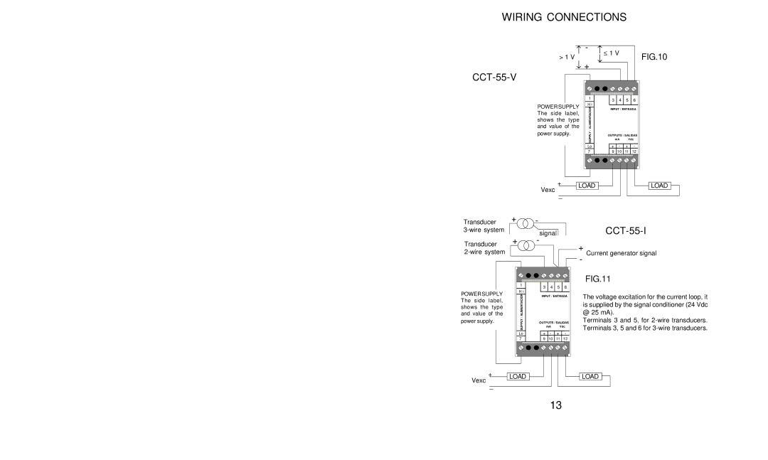
| FIG.10 | |
> 1 V | ↓ |
| |||
↓ | + |
|
|
|
|
|
|
|
| ||
CCT-55-V
|
|
|
|
|
|
| 1 | 3 | 4 | 5 | 6 |
|
|
| POWER SUPPLY | H i |
|
|
|
| |||
|
|
| ALIMENTACION | INPUT / ENTRADA | |||||||
|
|
| and value of the | ||||||||
|
|
| The | side | label, |
|
|
|
|
| |
|
|
| shows | the type |
|
|
|
|
| ||
|
|
| power supply. | / |
|
|
|
| |||
|
|
| SUPPLY | OUTPUTS / SALIDAS | |||||||
|
|
|
|
|
|
|
| mA | Vdc | ||
|
|
|
|
|
|
| Lo | + | - | + | - |
|
|
|
|
|
|
| 7 | 9 | 10 | 11 | 12 |
|
|
| Vexc | + | LOAD |
|
|
| LOAD | ||
|
|
|
|
|
|
| |||||
|
|
| _ |
|
|
|
|
|
| ||
|
|
|
|
|
|
|
|
|
|
| |
Transducer | + | - |
|
|
|
|
| ||||
| signal |
|
| ||||||||
Transducer | + | - |
|
| + |
|
|
|
| ||
|
|
|
|
|
|
|
| ||||
|
|
|
|
|
|
|
| ||||
|
|
|
|
| Current generator signal | ||||||
|
|
|
|
|
|
| - |
|
|
|
|
|
| 1 |
|
|
|
| FIG.11 |
|
|
| |
|
| 3 | 4 | 5 | 6 |
|
|
|
|
| |
|
| H i |
|
|
|
|
| ||||
POWER SUPPLY |
|
|
|
|
|
|
|
|
| ||
ALIMENTACION | INPUT / ENTRADA | @ 25 mA). |
|
|
| ||||||
and value of the |
|
|
|
|
|
|
| ||||
The side | label, |
|
|
|
|
| The voltage excitation for the current loop, it | ||||
shows the | type |
|
|
|
|
| is supplied by the signal conditioner (24 Vdc | ||||
|
|
|
|
|
|
|
|
|
| ||
power supply. | / |
|
|
|
| Terminals 3 and 5, for | |||||
SUPPLY | OUTPUTS / SALIDAS | ||||||||||
|
| mA | Vdc | Terminals 3, 5 and 6 for | |||||||
|
| Lo | + | - | + | - |
|
|
|
|
|
|
| 7 | 9 | 10 | 11 | 12 |
|
|
|
|
|
Vexc | + | LOAD |
|
|
|
|
| LOAD |
| |
| _ |
|
|
|
|
|
|
|
| |
|
|
|
|
|
|
|
|
| ||
|
|
|
|
|
|
|
|
|
| |
|
|
|
|
|
|
|
|
| ||
13