POWER SUPPLY module MA
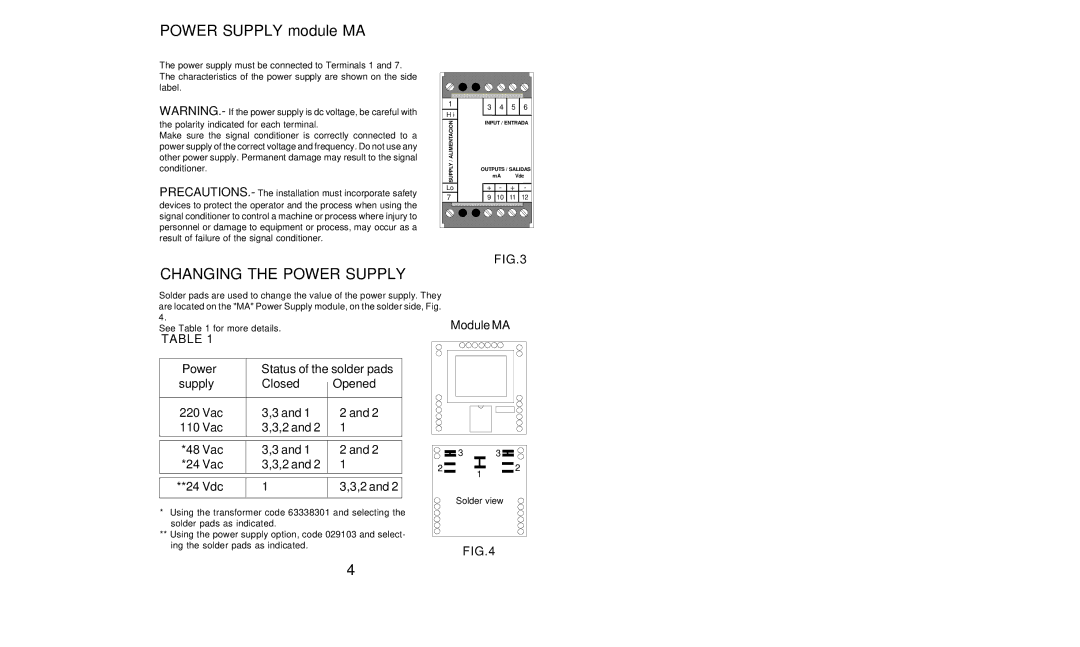
The power supply must be connected to Terminals 1 and 7. The characteristics of the power supply are shown on the side label.
WARNING.- If the power supply is dc voltage, be careful with the polarity indicated for each terminal.
Make sure the signal conditioner is correctly connected to a power supply of the correct voltage and frequency. Do not use any other power supply. Permanent damage may result to the signal conditioner.
PRECAUTIONS.- The installation must incorporate safety devices to protect the operator and the process when using the signal conditioner to control a machine or process where injury to personnel or damage to equipment or process, may occur as a result of failure of the signal conditioner.
1 | 3 | 4 | 5 | 6 | |
H i |
|
|
|
| |
/ ALIMENTACION | INPUT / ENTRADA | ||||
|
|
|
| ||
SUPPLY | OUTPUTS / SALIDAS | ||||
| mA | Vdc | |||
+ | - | + | - | ||
Lo | |||||
7 | 9 | 10 | 11 | 12 | |
|
| FIG.3 | |||
CHANGING THE POWER SUPPLY
Solder pads are used to change the value of the power supply. They |
|
are located on the "MA" Power Supply module, on the solder side, Fig. |
|
4. | Module MA |
See Table 1 for more details. |
TABLE 1
Power | Status of the solder pads | ||
supply | Closed |
| Opened |
| |||
|
|
|
|
220 Vac | 3,3 and 1 |
| 2 and 2 |
110 Vac | 3,3,2 and 2 |
| 1 |
|
|
|
|
|
|
|
|
*48 Vac | 3,3 and 1 |
| 2 and 2 |
*24 Vac | 3,3,2 and 2 |
| 1 |
|
|
|
|
|
|
|
|
**24 Vdc | 1 |
| 3,3,2 and 2 |
|
|
|
|
*Using the transformer code 63338301 and selecting the solder pads as indicated.
**Using the power supply option, code 029103 and select- ing the solder pads as indicated.
3 | 3 |
2 | 2 |
| 1 |
Solder view
FIG.4
4