FREQUENCY OUTPUT RANGE SELECTION
PULSES PER HOUR
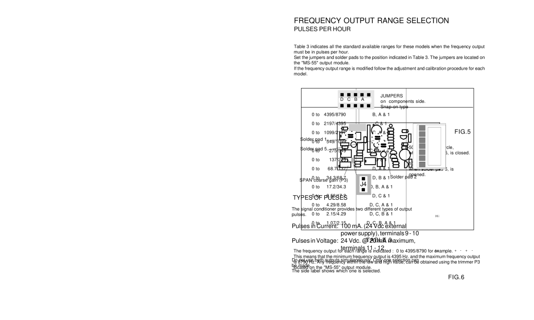
Table 3 indicates all the standard available ranges for these models when the frequency output must be in pulses per hour.
Set the jumpers and solder pads to the position indicated in Table 3. The jumpers are located on the
If the frequency output range is modified follow the adjustment and calibration procedure for each model.
PULSES / HOUR | CLOSE JUMPERS/ | PULSE WIDTH | ||
AND SOLDER PADS | ||||
|
|
| ||
|
|
|
| |
0 to | 4395/8790 | B, A & 1 |
| |
0 to | 2197/4395 | C & 1 |
| |
0 to | 1099/2197 | C, A & 1 |
| |
0 to | 549/1099 | C, B & 1 |
| |
0 to | 275/549 | C, B, A & 1 | 50 % of the full cycle, | |
when solder pad 5, is closed. | ||||
|
|
| ||
0 to | 137/275 | D & 1 | 100 mS. | |
|
|
| ||
0 to | 68.7/137 | D, A & 1 | when solder pad 5, is | |
0 to | 34.3/68.7 | D, B & 1 | opened. | |
| ||||
0 to | 17.2/34.3 | D, B, A & 1 |
| |
0 to | 8.58/17.2 | D, C & 1 |
| |
0 to | 4.29/8.58 | D, C, A & 1 |
| |
0 to | 2.15/4.29 | D, C, B & 1 |
| |
0 to | 1.07/2.15 | D, C, B, A & 1 |
| |
|
|
|
| |
TABLE 3
The frequency output for each range is indicated : 0 to 4395/8790 for example.
This means that the minimum frequency output is 4395 Hz. and the maximum frequency output is 8790 Hz. Any frequency within the low and high value, can be obtained using the trimmer P3 located on the
7
