4 REGISTER ARCHITECTURE
The
4.1 Control & Data Registers
The
The first address, or BASE ADDRESS, is determined by the setting of a bank of switches on the board.
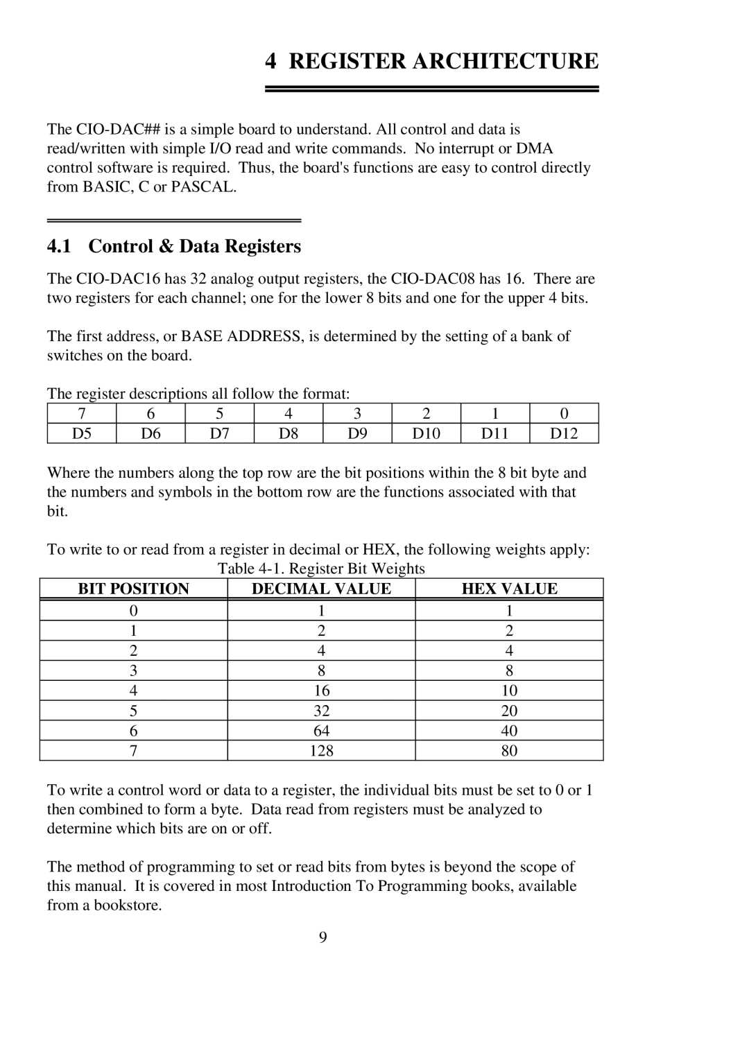
The register descriptions all follow the format:
7 | 6 | 5 | 4 | 3 | 2 | 1 | 0 |
D5 | D6 | D7 | D8 | D9 | D10 | D11 | D12 |
Where the numbers along the top row are the bit positions within the 8 bit byte and the numbers and symbols in the bottom row are the functions associated with that bit.
To write to or read from a register in decimal or HEX, the following weights apply:
Table
BIT POSITION | DECIMAL VALUE | HEX VALUE |
|
|
|
0 | 1 | 1 |
1 | 2 | 2 |
2 | 4 | 4 |
3 | 8 | 8 |
4 | 16 | 10 |
5 | 32 | 20 |
6 | 64 | 40 |
7 | 128 | 80 |
To write a control word or data to a register, the individual bits must be set to 0 or 1 then combined to form a byte. Data read from registers must be analyzed to determine which bits are on or off.
The method of programming to set or read bits from bytes is beyond the scope of this manual. It is covered in most Introduction To Programming books, available from a bookstore.
9