Manuals
/
Omega Engineering
/
Power Tools
/
Stud Sensor
Omega Engineering
FLR1000
manual
Models:
FLR1000
1
22
29
29
Download
29 pages
30.58 Kb
19
20
21
22
23
24
25
26
Troubleshooting
Specs
Install
Connecting a Cable Assembly
Dimension
Maintenance
Zero Adjustments
Page 22
Image 22
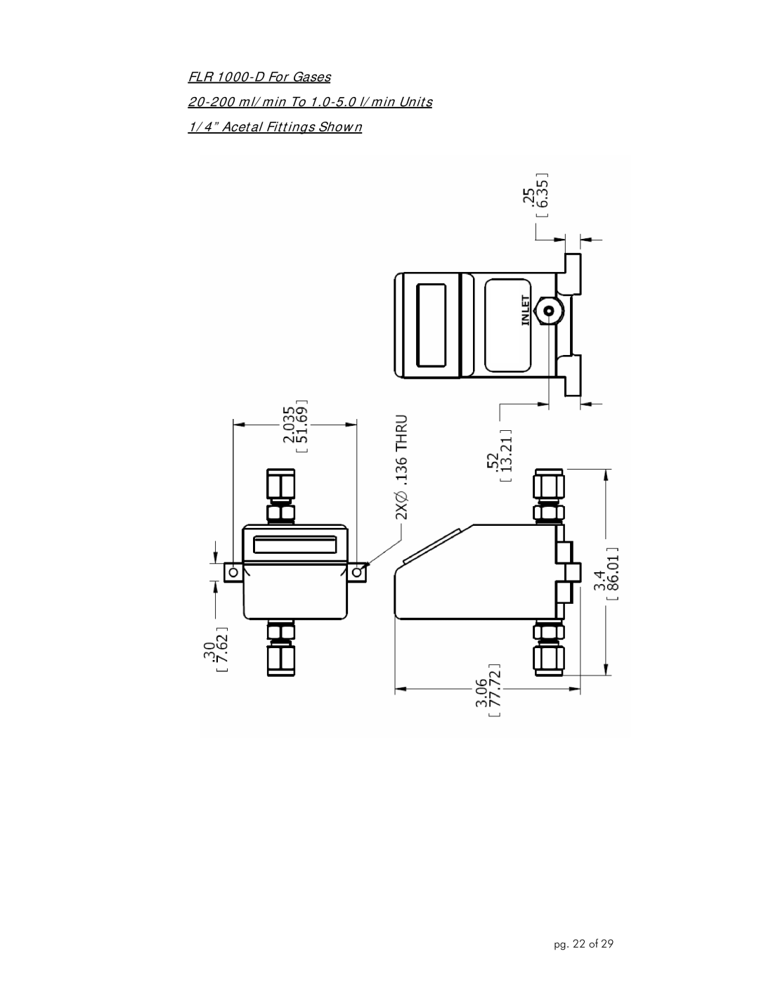
FLR
1000-D
For Gases
20-200
ml/min To
1.0-5.0
l/min Units 1/4” Acetal Fittings Shown
pg. 22 of 29
Page 21
Page 23
Page 22
Image 22
Page 21
Page 23
Contents
FLR 1000 & 1000-BR Series Flow Sensors & Meters For Gases
Page
B L E O F C O N T E N T S
Unpacking
Introduction
Product Overview and Principle of Operation
Installation
General Considerations
Mounting the Flow Sensor or Flow Meter
Tubing Connections
Electrical Connections Overview
Connecting a Cable Assembly
Electrical Connections Voltage Output Units
Using a 0-5VDC Output Power Adapter Package
Flow Readings
Operation
Start Up
5VDC Analog Outputs
Flows Above the Maximum Rated Flow
Operating at Flow Rates Outside the Calibrated Flow Range
Flows Below the Minimum Rated Flow
Recalibration
Zero Adjustments
Using Flow Sensors or Flow Meters with Different Gases
Corrected Flow = Flow reading X Correction Factor
Page
General
Maintenance and Product Care
Cleaning and Flushing
Returning Units for Repair or Recalibration
Specifications For Gas Units
FLR1000 FLR1000-D FLR1000-BR-D
Connector Pin And Wire Color Cross Reference
Pin Cable Wire Color Description
Dimensions
FLR 1000 For Gases 10.0 l/min Units Acetal Fittings Shown
Page
Page
Page
Page
Page
Troubleshooting Guide
Symptom Possible Cause Method of Correction
Symptom Possible Cause Method of Correction
Page
M4575/0807 pg
Top
Page
Image
Contents