proven design minimizes zero drift while maintaining fast response and linear outputs with virtually no maintenance.
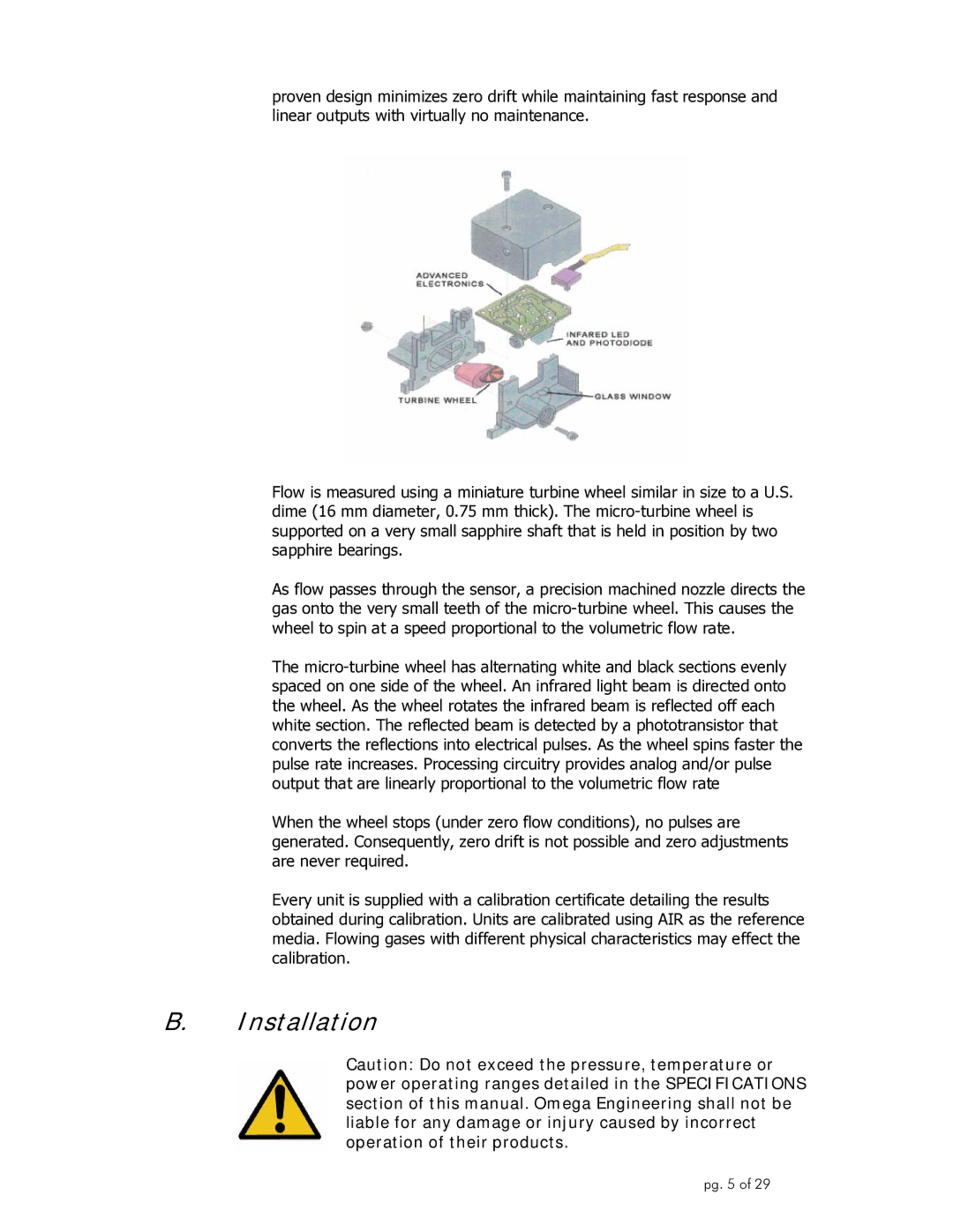
Flow is measured using a miniature turbine wheel similar in size to a U.S. dime (16 mm diameter, 0.75 mm thick). The
As flow passes through the sensor, a precision machined nozzle directs the gas onto the very small teeth of the
The
When the wheel stops (under zero flow conditions), no pulses are generated. Consequently, zero drift is not possible and zero adjustments are never required.
Every unit is supplied with a calibration certificate detailing the results obtained during calibration. Units are calibrated using AIR as the reference media. Flowing gases with different physical characteristics may effect the calibration.
B.Installation
Caution: Do not exceed the pressure, temperature or power operating ranges detailed in the SPECIFICATIONS section of this manual. Omega Engineering shall not be liable for any damage or injury caused by incorrect operation of their products.
pg. 5 of 29