Initial Set-Up in Eight Easy Steps
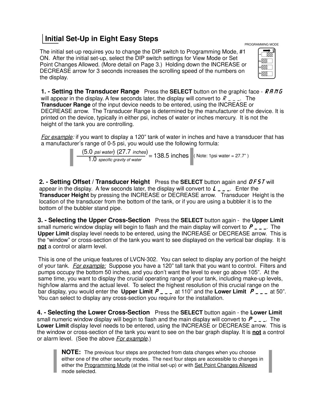
PROGRAMMING MODE
The initial
1
2![]()
![]()
3![]()
4![]()
![]()
ON
1.- Setting the Transducer Range Press the SELECT button on the graphic face - RANG will appear in the display. A few seconds later, the display will convert to R___. The Transducer Range of the input device needs to be entered, using the INCREASE or DECREASE arrow. The Transducer Range is determined by the manufacturer of the device. It is printed on the device, typically in either psi, inches of water or inches mercury. It is not the height of the tank you are controlling.
For example: if you want to display a 120” tank of water in inches and have a transducer that has a manufacturer’s range of
(5.0 psi water) (27.7 inches)= 138.5 inches ![]() ( Note: 1psi water = 27.7” ) 1.0 specific gravity of water
( Note: 1psi water = 27.7” ) 1.0 specific gravity of water
2.- Setting Offset / Transducer Height Press the SELECT button again and OFST will appear in the display. A few seconds later, the display will convert to L___. Enter the Transducer Height by pressing the INCREASE or DECREASE arrow. Transducer Height is the location of the transducer from the bottom of the tank, or if you are using a bubbler it is to the bottom of the bubbler stand pipe.
3. - Selecting the Upper
This is one of the unique features of
4.- Selecting the Lower
NOTE: The previous four steps are protected from data changes when you choose either one of the other security modes. The next four steps are accessible to changes in either the Programming Mode (at the initial