PCI-DIO96 specifications
The Omega Engineering PCI-DIO96 is a versatile and high-performance digital input/output board designed for a wide range of industrial automation and data acquisition applications. With its robust features and advanced technologies, the PCI-DIO96 stands out in the field of digital I/O expansion cards.At the core of the PCI-DIO96 is its capability to handle 96 digital I/O channels, making it suitable for applications that require extensive control and monitoring. The board is equipped with 96 lines that can be individually configured as input or output, providing flexibility to manage various digital devices such as sensors, valves, and relays. This configuration is particularly beneficial in complex systems where a mix of digital signals is needed.
One of the most notable characteristics of the PCI-DIO96 is its high-speed operation. The board supports data transfer rates that can accommodate demanding applications, enabling rapid response times crucial in industrial environments. This high-speed capability ensures that it can keep up with the fast-paced demands of modern automation processes.
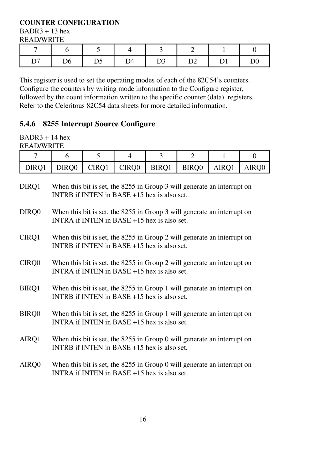
The PCI-DIO96 also includes additional features such as programmable timers and counters, allowing for precise control and measurement of time-sensitive processes. This performance enhancement is especially useful in applications requiring synchronization of multiple digital signals or sequential operations.
Another significant advantage of the PCI-DIO96 is its compatibility with various operating systems and widely-used programming environments. It can be seamlessly integrated with popular data acquisition and control software, providing users with a familiar setup process. This ease of integration diminishes the time required for installation and setup, allowing for quicker deployment in projects.
The hardware design of the PCI-DIO96 also emphasizes reliability and ease of use. The board is built with durable components to withstand the rigors of industrial settings, ensuring longevity and reliability in various conditions. Additionally, its straightforward installation process translates into minimal downtime during setup.
In conclusion, the Omega Engineering PCI-DIO96 is a powerful digital I/O board that combines extensive channel capacity, high-speed performance, and robust features. Its versatility makes it an ideal choice for diverse applications in industrial automation, offering reliability and ease of integration that professionals in the field seek for their projects. Whether for monitoring, control, or data acquisition, the PCI-DIO96 remains a trusted solution for engineers and technicians alike.
