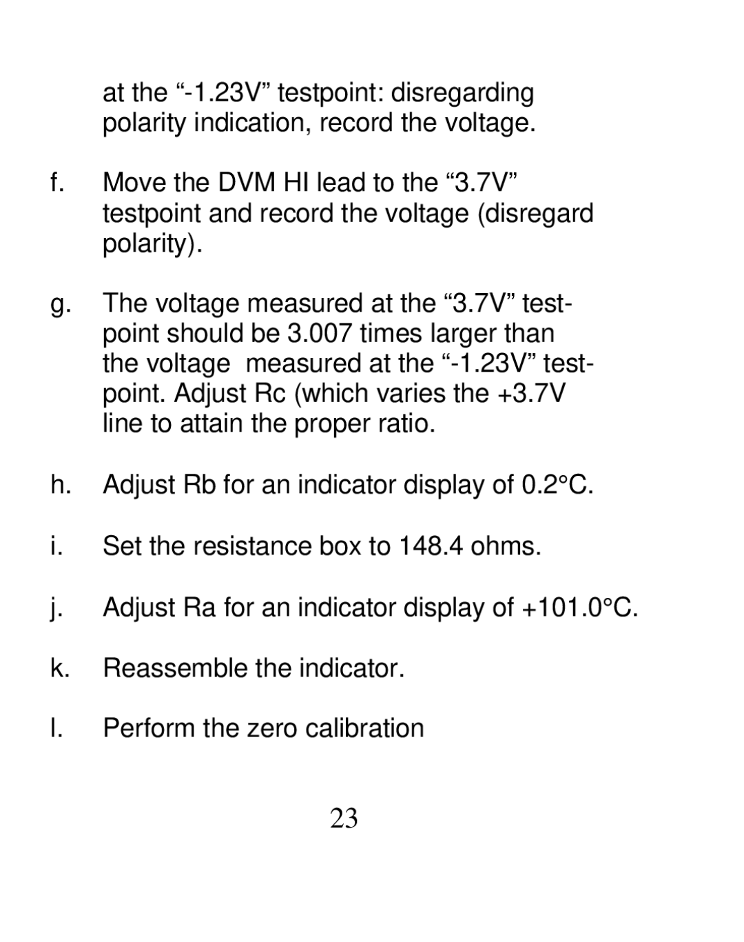
at the
f.Move the DVM HI lead to the “3.7V” testpoint and record the voltage (disregard polarity).
g.The voltage measured at the “3.7V” test- point should be 3.007 times larger than the voltage measured at the
h.Adjust Rb for an indicator display of 0.2°C.
i.Set the resistance box to 148.4 ohms.
j.Adjust Ra for an indicator display of +101.0°C.
k.Reassemble the indicator.
l.Perform the zero calibration
23
