2.4.1Interrupt Block Diagram of OME-PIO-
D56/D24 |
|
| INT_CHAN_0 |
INT\ | INT_CHAN_1 |
| |
Level_trigger | INT_CHAN_2 |
| |
| INT_CHAN_3 |
| initial_low |
| active_high |
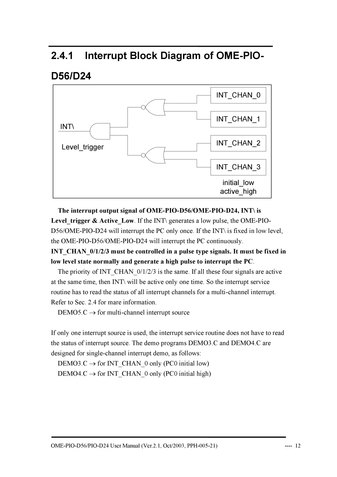
The interrupt output signal of OME-PIO-D56/OME-PIO-D24, INT\ is
Level_trigger & Active_Low. If the INT\ generates a low pulse, the
INT_CHAN_0/1/2/3 must be controlled in a pulse type signals. It must be fixed in low level state normally and generate a high pulse to interrupt the PC.
The priority of INT_CHAN_0/1/2/3 is the same. If all these four signals are active at the same time, then INT\ will be active only one time. So the interrupt service routine has to read the status of all interrupt channels for a
DEMO5.C → for
If only one interrupt source is used, the interrupt service routine does not have to read the status of interrupt source. The demo programs DEMO3.C and DEMO4.C are designed for
DEMO3.C → for INT_CHAN_0 only (PC0 initial low) DEMO4.C → for INT_CHAN_0 only (PC0 initial high)