Section |
Connecting Link Adapter AL004-(P)E
When using a Link Adapter, connect both
Host computer |
| Link Adapter |
|
|
| Host Link Unit | |||||
|
|
|
|
|
|
|
|
|
| ||
1 | FG |
| FG | 1 | 7 | FG |
|
|
| FG | 7 |
|
|
| |||||||||
7 | SG | SG | 7 | 3 | SG |
| SG | 3 | |||
2 | SD | SD | 2 | 9 | SDA |
| SDA | 9 | |||
3 | RD | RD | 3 | 5 | SDB |
| SDB | 5 | |||
|
|
|
|
| 6 | RDA |
| RDA 6 | |||
|
|
|
|
| 1 | RDB |
| RDB 1 | |||
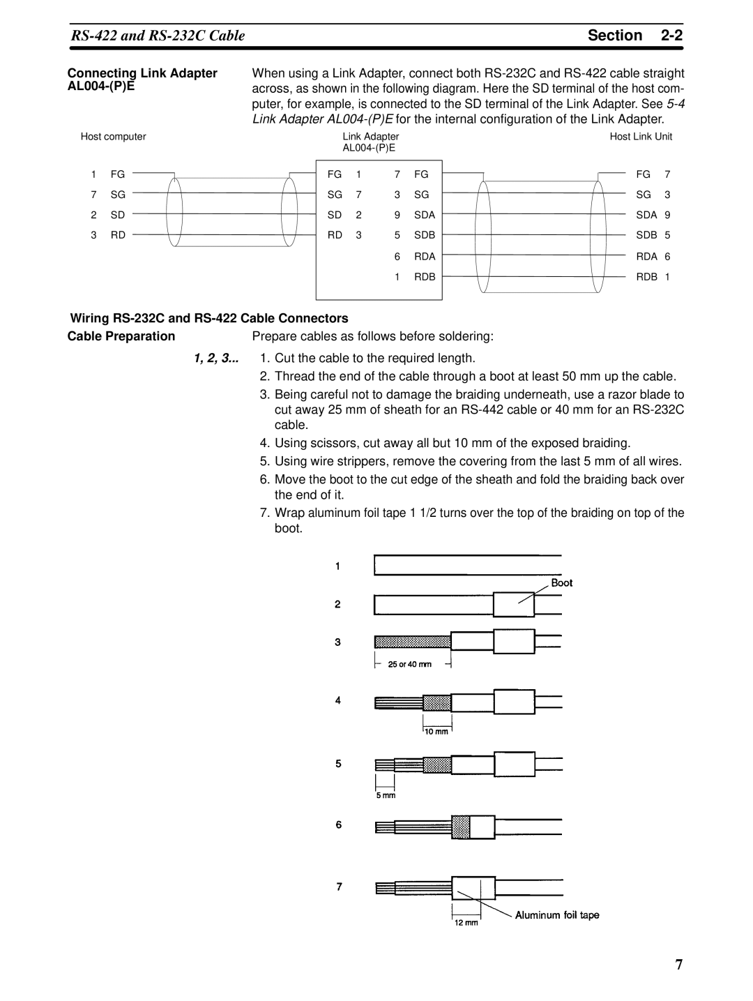
Wiring
Cable Preparation | Prepare cables as follows before soldering: |
1, 2, 3... 1. Cut the cable to the required length.
2.Thread the end of the cable through a boot at least 50 mm up the cable.
3.Being careful not to damage the braiding underneath, use a razor blade to cut away 25 mm of sheath for an
4.Using scissors, cut away all but 10 mm of the exposed braiding.
5.Using wire strippers, remove the covering from the last 5 mm of all wires.
6.Move the boot to the cut edge of the sheath and fold the braiding back over the end of it.
7.Wrap aluminum foil tape 1 1/2 turns over the top of the braiding on top of the boot.
7