| Backup Power Supply | Section |
|
|
| When total transmission loss from the system is subtracted from the transmit/re- | |
|
| ceive differential of the Link Adapters, the margin must be at least 4 dB. To deter- | |
|
| mine total transmission loss, first calculate the loss over the cable by multiplying | |
|
| the loss/km by the total length of the cable. Then calculate the loss at the con- | |
|
| nections by multiplying the loss/connection by the number of connections. Final- | |
|
| ly, add the cable loss and the connector loss. Subtract this figure, the total trans- | |
|
| mission loss, from the transmit/receive differential. If the difference is greater | |
|
| than 4 dB, then the cable length is acceptable. | |
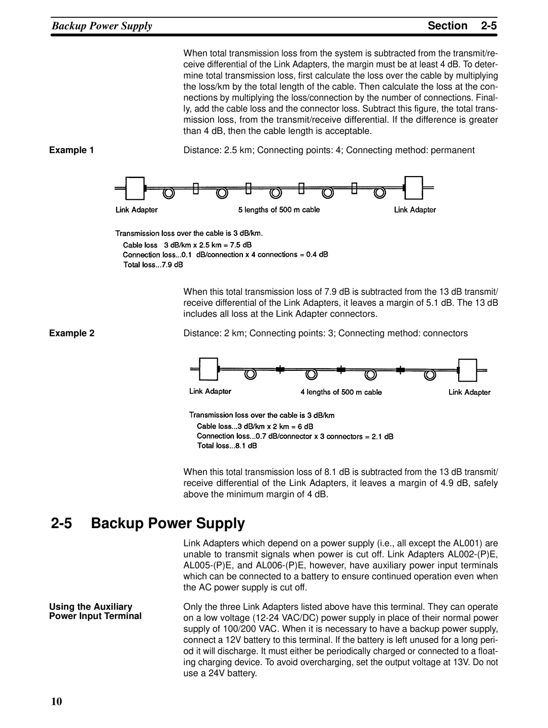
Example 1 | Distance: 2.5 km; Connecting points: 4; Connecting method: permanent | ||
| When this total transmission loss of 7.9 dB is subtracted from the 13 dB transmit/ |
| receive differential of the Link Adapters, it leaves a margin of 5.1 dB. The 13 dB |
| includes all loss at the Link Adapter connectors. |
Example 2 | Distance: 2 km; Connecting points: 3; Connecting method: connectors |
When this total transmission loss of 8.1 dB is subtracted from the 13 dB transmit/ receive differential of the Link Adapters, it leaves a margin of 4.9 dB, safely above the minimum margin of 4 dB.
2-5 Backup Power Supply
Using the Auxiliary Power Input Terminal
Link Adapters which depend on a power supply (i.e., all except the AL001) are unable to transmit signals when power is cut off. Link Adapters
Only the three Link Adapters listed above have this terminal. They can operate on a low voltage
10