Omron C-series manual PC Link Systems, Example

Models: C-series

1 43
Download 43 pages 31.93 Kb
Page 27
Image 27

PC Link Systems

Section 4-1

4-1 PC Link Systems


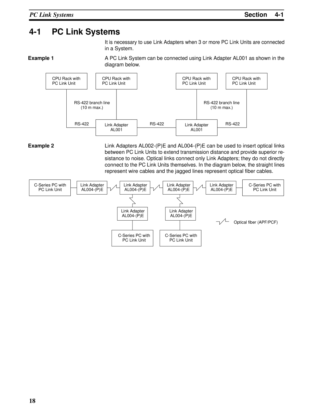
It is necessary to use Link Adapters when 3 or more PC Link Units are connected


in a System.

Example 1

A PC Link System can be connected using Link Adapter AL001 as shown in the


diagram below.

CPU Rack with


CPU Rack with

PC Link Unit


PC Link Unit


RS-422 branch line

(10 m max.)

RS-422

Link Adapter


AL001


RS-422

CPU Rack with


CPU Rack with

PC Link Unit


PC Link Unit


RS-422 branch line

(10 m max.)

Link Adapter

RS-422

AL001


Example 2

C-Series PC with

PC Link Unit

Link Adapters AL002-(P)E and AL004-(P)E can be used to insert optical links between PC Link Units to extend transmission distance and provide superior re- sistance to noise. Optical links connect only Link Adapters; they do not directly connect to the PC Link Units themselves. In the diagram below, the straight lines represent wire cables and the jagged lines represent optical fiber cables.


Link Adapter


Link Adapter


Link Adapter


Link Adapter


C-Series PC with


AL004-(P)E


AL004-(P)E


AL004-(P)E


AL004-(P)E


PC Link Unit


Link Adapter

AL004-(P)E

C-Series PC with

PC Link Unit

Link Adapter

AL004-(P)E

Optical fiber (APF/PCF)

C-Series PC with

PC Link Unit

18

Page 27
Image 27
Omron C-series manual PC Link Systems, Example