Control Position and Names
Front Panel
For operational instructions, see the page indicated in brackets [ ].
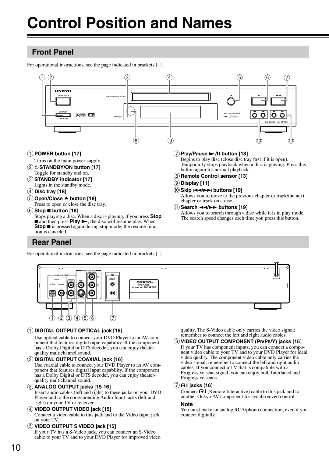
1POWER button [17] | 7Play/Pause £/8 button [18] | |||
Turns on the main power supply. | Begins to play disc (close disc tray first if it is open). | |||
2 |
| STANDBY/ON button [17] | Temporarily stops playback when a disc is playing. Press this | |
| ||||
| button again for normal playback. | |||
Toggle for standby and on. | ||||
8Remote Control sensor [13] | ||||
3STANDBY indicator [17] | ||||
9Display [11] | ||||
Lights in the standby mode. | ||||
0Skip 4/¢ buttons [19] | ||||
4Disc tray [18] | ||||
5Open/Close 0 button [18] | Allows you to move to the previous chapter or track/the next | |||
chapter or track on a disc. | ||||
Press to open or close the disc tray. | ||||
ASearch 1/¡ buttons [19] | ||||
6Stop 7 button [18] | ||||
Allows you to search through a disc while it is in play mode. | ||||
Stops playing a disc. When a disc is playing, if you press Stop | ||||
The search speed changes each time you press this button. | ||||
7 and then press Play £, the disc will resume play. When | ||||
| ||||
Stop 7 is pressed again during stop mode, the resume func- |
| |||
tion is canceled. |
| |||
Rear Panel
For operational instructions, see the page indicated in brackets [ ].
VIDEO OUTPUT
|
| COMPONENT |
AUDIO OUTPUT | PR | |
|
| |
DIGITAL | ANALOG | VIDEO |
|
| |
OPTICAL COAXIAL L |
| PB |
REMOTE CONTROL
DVD PLAYER
MODEL NO.
RY
S VIDEO
1DIGITAL OUTPUT OPTICAL jack [16]
Use optical cable to connect your DVD Player to an AV com- ponent that features digital input capability. If the component has a Dolby Digital or DTS decoder, you can enjoy theater- quality multichannel sound.
2DIGITAL OUTPUT COAXIAL jack [16]
Use coaxial cable to connect your DVD Player to an AV com- ponent that features digital input capability. If the component has a Dolby Digital or DTS decoder, you can enjoy theater- quality multichannel sound.
3ANALOG OUTPUT jacks [15-16]
Insert audio cables (left and right) to these jacks on your DVD Player and to the corresponding Audio Input jacks (left and right) on your TV or receiver.
4VIDEO OUTPUT VIDEO jack [15]
Connect a video cable to this jack and to the Video Input jack on your TV.
5VIDEO OUTPUT S VIDEO jack [15]
If your TV has a
quality. The
6VIDEO OUTPUT COMPONENT (PR/PB/Y) jacks [15]
If your TV has component inputs, you can connect a compo- nent video cable to your TV and to your DVD Player for ideal video quality. The component video cable only carries the video signal; remember to connect the left and right audio cables. If you connect a TV that is compatible with a Progressive scan signal, you can enjoy both Interlaced and Progressive scans.
7 jacks [16]
Connect ![]() (Remote Interactive) cable to this jack and to another Onkyo AV component for synchronized control.
(Remote Interactive) cable to this jack and to another Onkyo AV component for synchronized control.
Note
You must make an analog RCA/phono connection, even if you connect digitally.
10
