Front & Rear Panels—Continued
Rear Panel
1 | 2 3 45 6 | 7 | 8 | 9 | |||
| AUDIO OUTPUT |
| COMPONENT | REMOTE |
|
| |
| DIGITAL | Y | PB | L |
|
| |
|
| CONTROL |
|
| |||
OPTICAL | COAXIAL |
|
| AUDIO |
| AV CONNECTOR | AC INLET |
|
|
|
|
|
|
| |
|
|
|
| OUTPUT |
|
|
|
|
|
|
| ANALOG |
|
|
|
|
|
|
| R |
|
| MODEL NO. |
|
| S VIDEO | VIDEO |
|
|
| |
|
| PR |
|
|
| ||
VIDEO OUTPUT
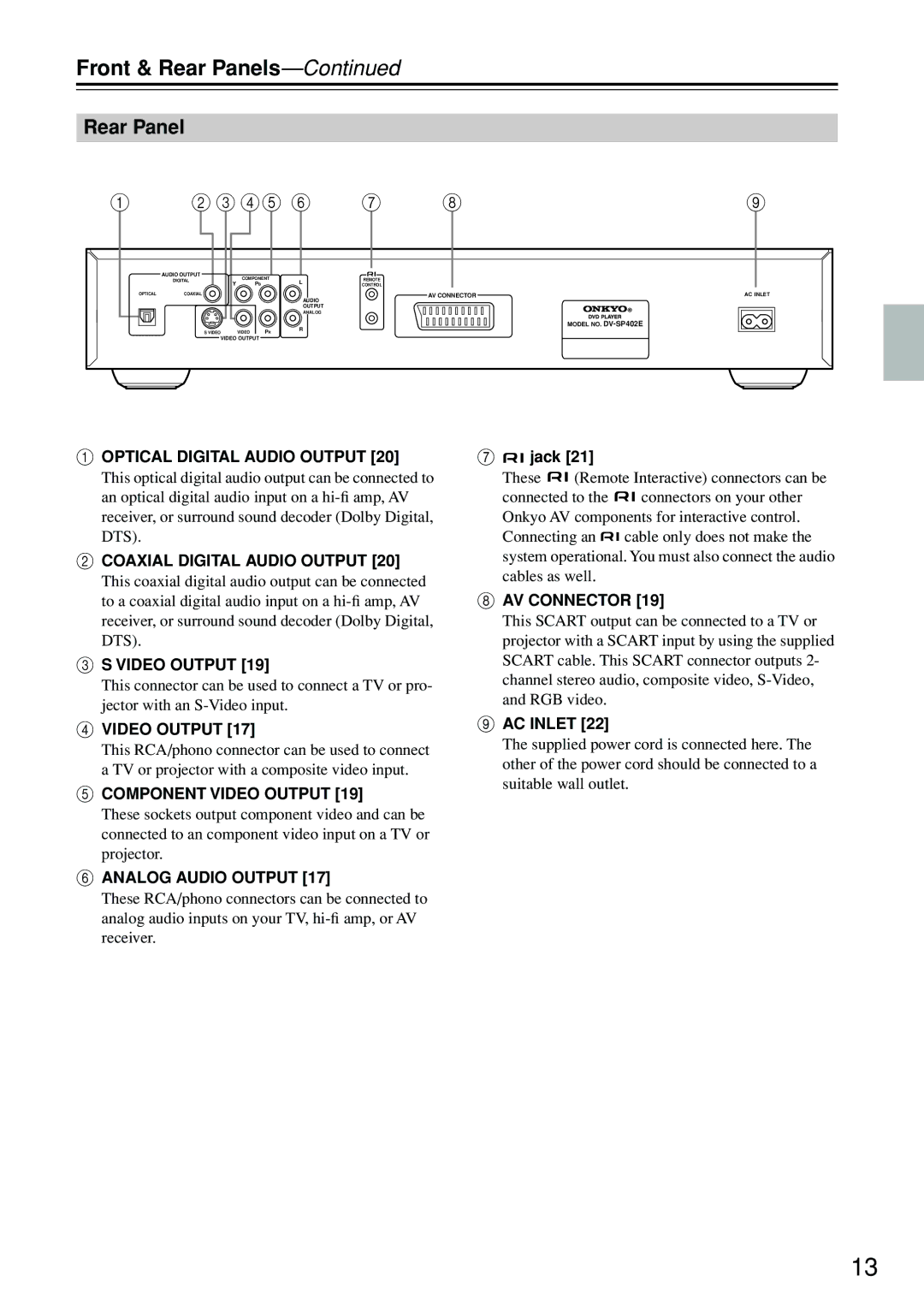
AOPTICAL DIGITAL AUDIO OUTPUT [20]
This optical digital audio output can be connected to an optical digital audio input on a
BCOAXIAL DIGITAL AUDIO OUTPUT [20]
This coaxial digital audio output can be connected to a coaxial digital audio input on a
CS VIDEO OUTPUT [19]
This connector can be used to connect a TV or pro- jector with an
DVIDEO OUTPUT [17]
This RCA/phono connector can be used to connect a TV or projector with a composite video input.
ECOMPONENT VIDEO OUTPUT [19]
These sockets output component video and can be connected to an component video input on a TV or projector.
FANALOG AUDIO OUTPUT [17]
G
 jack [21]
These ![]()
![]() (Remote Interactive) connectors can be
(Remote Interactive) connectors can be
connected to the ![]()
![]() connectors on your other Onkyo AV components for interactive control.
connectors on your other Onkyo AV components for interactive control.
Connecting an ![]()
![]() cable only does not make the system operational. You must also connect the audio cables as well.
cable only does not make the system operational. You must also connect the audio cables as well.
HAV CONNECTOR [19]
This SCART output can be connected to a TV or projector with a SCART input by using the supplied SCART cable. This SCART connector outputs 2- channel stereo audio, composite video,
IAC INLET [22]
The supplied power cord is connected here. The other of the power cord should be connected to a suitable wall outlet.
These RCA/phono connectors can be connected to analog audio inputs on your TV,
13