Connecting the DVD player
Before Making Any Connections
•Read the manuals supplied with your AV components.
•Don’t connect the power cord until you’ve completed all audio and video connections.
Optical Digital Outputs
The DVD player’s optical digital connectors have a shut-
Caution: To prevent shutter damage, hold the optical plug straight when inserting and removing.
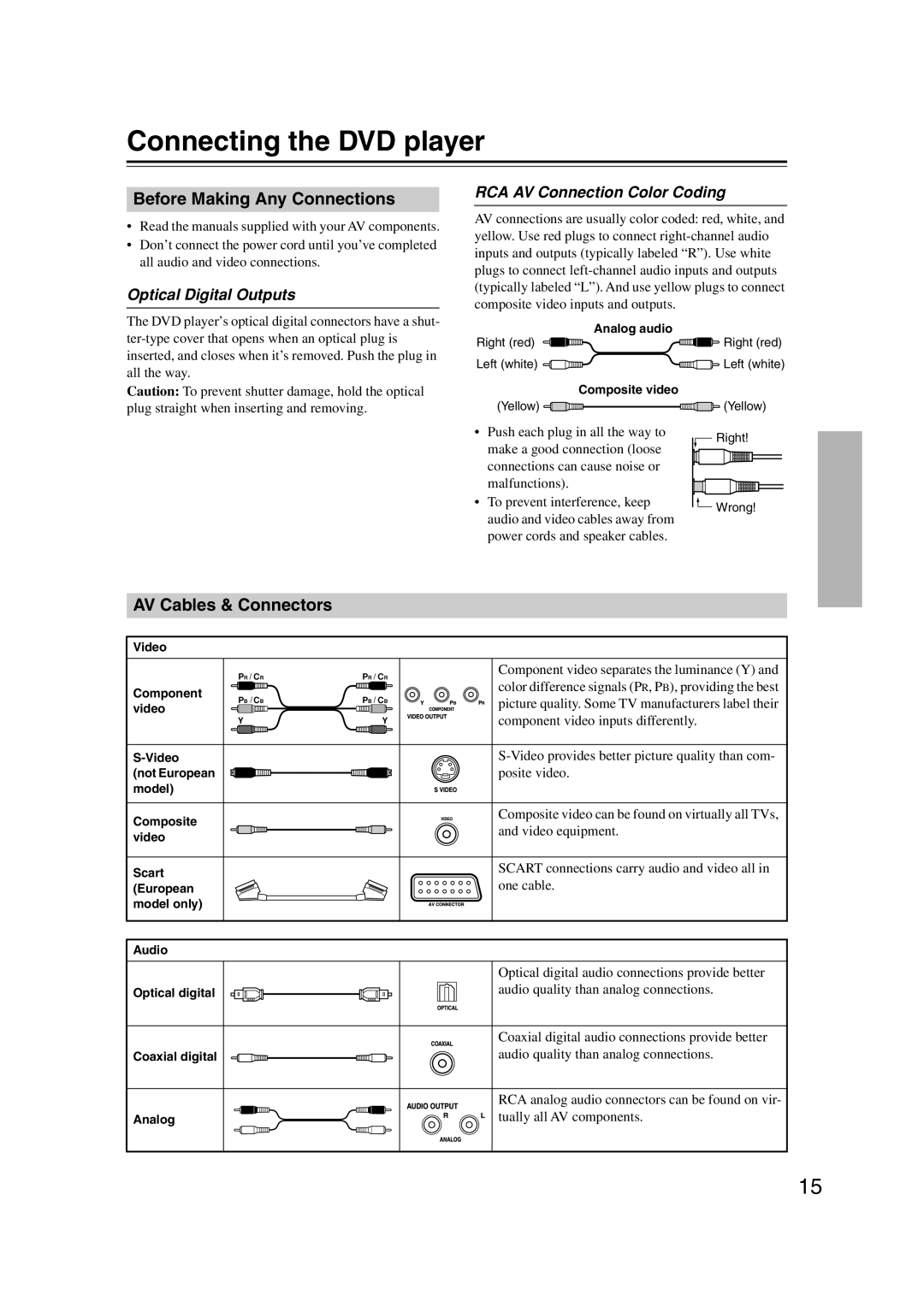
RCA AV Connection Color Coding
AV connections are usually color coded: red, white, and yellow. Use red plugs to connect
Analog audio |
| |
Right (red) | Right (red) | |
Left (white) | Left (white) | |
Composite video |
| |
(Yellow) | (Yellow) | |
• Push each plug in all the way to | Right! | |
make a good connection (loose | ||
| ||
connections can cause noise or |
| |
malfunctions). |
| |
• To prevent interference, keep | Wrong! | |
audio and video cables away from | ||
| ||
power cords and speaker cables. |
|
AV Cables & Connectors
Video
PR / CR | PR / CR | Component video separates the luminance (Y) and | |
color difference signals (PR, PB), providing the best | |||
Component |
| ||
PB / CB |
| ||
PB / CB | picture quality. Some TV manufacturers label their | ||
video |
| ||
| component video inputs differently. | ||
Y | Y | ||
| |||
(not European |
| posite video. | |
model) |
|
| |
Composite |
| Composite video can be found on virtually all TVs, | |
| and video equipment. | ||
video |
| ||
|
| ||
Scart |
| SCART connections carry audio and video all in | |
| one cable. | ||
(European |
| ||
model only) |
|
| |
Audio |
|
|
Optical digital
Coaxial digital
Analog
Optical digital audio connections provide better audio quality than analog connections.
Coaxial digital audio connections provide better audio quality than analog connections.
RCA analog audio connectors can be found on vir- tually all AV components.
15