HT-SR800
Important Safety Instructions
Avis
FCC Information for User
Precautions
Power
Speaker Precautions
Placement
Using Close to a TV or Computer
Input Signal Warning
Speaker set a Speaker set B Indicator Output
Enjoying Home Theater
Speaker Sets a and B
Center speaker
Package Contents
Features
Setup
Automatic Speaker Setup
Hdmi Video
Digital Input Input Display
Contents
Getting to Know the AV Receiver
Front Panel
Getting to Know the AV Receiver
Display
Digital in Optical 1, 2 and Coaxial 1
Hdmi in 1, 2, and OUT
Sirius antenna North American models only
XM antenna North American models only
Aiming the Remote Controller
Remote Controller
Installing the Batteries
RECEIVER/TAPE Mode
Remote Controller
Using the Remote Controller
Listening Mode buttons
Remote Mode buttons
Buttons used when the Tuner input is selected
Buttons used when the Tape input is selected
DVD Mode
CD/MD/CDR/DOCK Mode
To select the input source, press
DISC/ALBUM +/- button
Arrow / and Enter buttons
Speakers
Subwoofer SKW-550
Connecting Your Speakers
Enjoying Home Theater
Front left and right speakers SKF-550F
Surround back left and right speakers SKB-550
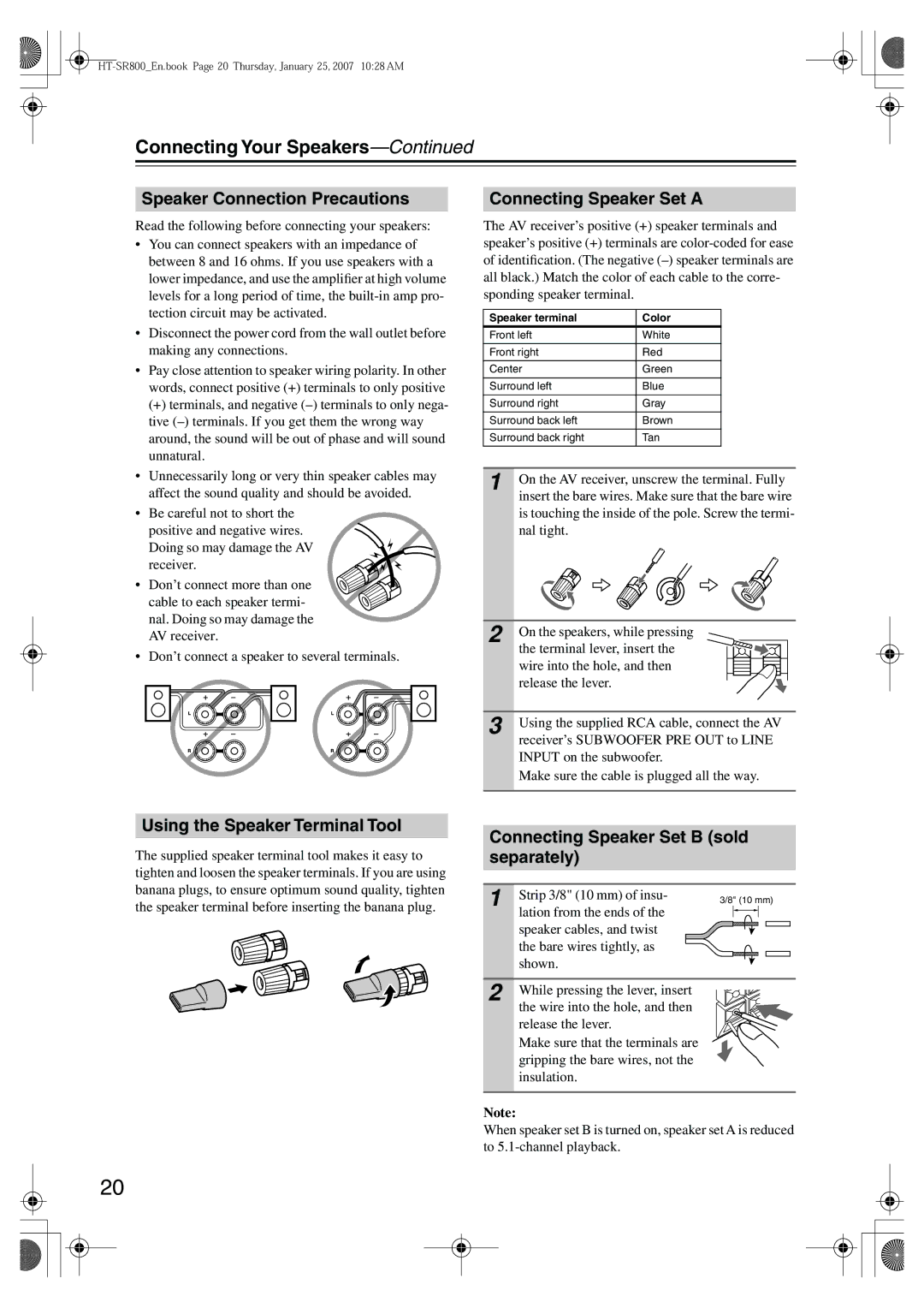
Connecting Your Speakers
Speaker Connection Precautions
Connecting Speaker Set a
Using the Speaker Terminal Tool
Wall Mounting
SKF-550F
Connecting Antennas
Connecting the AM Loop Antenna
Connecting the Indoor FM Antenna
Attach the FM antenna, as shown American Model
Connecting Antennas
Using a TV/FM Antenna Splitter
Connecting Your Components
About AV Connections
Optical Digital Jacks
AV Connection Color Coding
Connecting Your Components
Connecting Audio and Video Signals to the AV Receiver
Which Connections Should I Use?
Audio Connection Formats
Connecting a TV or Projector
Hint
DVD player
Connecting a DVD player
Choose a video connection from a , B , and C
Hooking Up the Multichannel DVD Input
DVD player Step
Connecting Components with Hdmi
Assign the Hdmi
Connecting a VCR or DVD Recorder for Playback
VCR or DVD recorder
VCR
DVD recorder
Connecting a VCR or DVD Recorder for Recording
Connecting a Camcorder, Games Console, or Other Device
Choose a video connection from a and B
Make the video connection a Make the audio connection a
Video source
Satellite, cable, set-top box, etc
Connecting a CD Player or Turntable
CD Player or Turntable MM with Built-in Phono Preamp Step
Connecting an RI Dock
Connecting a Cassette, CDR, MiniDisc, or DAT Recorder
RI Dock with video
RI Dock without video
Connecting Onkyo Components
Connecting the Power Cord
Auto Power On/Standby
Remote Control
Smooth Operation in a Few Easy Steps
Turning On the AV Receiver
Turning On and Standby
Measurement Points
First Time Setup
Automatic Speaker Setup Audyssey 2EQ/HTIB
First Time Setup
Using Audyssey 2EQ/HTIB
Error Messages
Changing the Speaker Settings Manually
To Retry the Automatic Speaker Setup
Using a Powered Subwoofer
Hdmi Video Setup
Digital Audio Input Setup
Changing the Input Display
Select a suitable listening mode and enjoy
See Using the Listening Modes on
Playing Your AV Components
Basic AV Receiver Operation
Displaying Source Information
Using the Multichannel DVD Input
Playing Your AV Components
Listening to AM/FM Stations
Tuning into AM/FM Radio Stations
Listening to the Radio
Presetting AM/FM Stations
Listening to the Radio
Adjusting the Bass and Treble
Setting the Display Brightness
Common Functions
Muting the AV Receiver
Using the Sleep Timer
Adjusting Speaker Levels
Using Headphones
Common Functions
Using the Listening Modes
Selecting with the Remote Controller
Selecting Listening Modes
Selecting on the AV Receiver
Using the Listening Modes
DVD
About the Listening Modes
DTS
Onkyo Original DSP Modes
Using the Late Night Function Dolby Digital only
Using the CinemaFILTER
Using the Audio Adjust Settings
Input Channel Settings
Plii and PLIIx Music Mode Settings
DTS Neo6 Music Mode Setting
Dolby Digital EX Input Signal Setting
Listening Angle Setting
Multichannel Subwoofer Setting
Lstn Angl Listening Angle
SW Sens
Recording Audio and Video from Separate Sources
Recording
Recording the Input Source
Speaker Configuration
Advanced Setup
Advanced Speaker Settings
Advanced Setup
Crossover Frequency
Double Bass
Speaker Distance
Speaker Levels
Buttons to select Equalizer,
Equalizer Settings
Setup menu closes
Digital Input Signal Formats
Correcting Sound and Picture Sync
Entering Remote Control Codes
Controlling Other Components
Remote Control Codes for Onkyo Components Connected via
Resetting Remote Mode Buttons
Resetting the Remote Controller
Controlling Other Components
STANDBY/ON, TV
TV VOL
CH +
Operates the VCR
Troubleshooting
Troubleshooting
Sound changes when I connect my head
Remote controller doesn’t work
Can’t record
Can’t control other components
Memory Backup
Specifications
Amplifier Section
Video Section
Tuner Section
Powered Subwoofer SKW-550 Center Speaker SKC-550C
Specifications
1ch Home Theater Speaker Package
Front Speaker SKF-550F
Memo
Onkyo U.S.A. Corporation
Onkyo Europe Electronics GmbH
Onkyo Europe UK Office
Onkyo China Limited