Important: Do not cut these wires. If you cut any wire, you cannot obtain a refund or exchange on this product. However, your local RadioShack store will provide warranty service if you cut a wire and find the product is defective.
You might need additional wire, de- pending on your individual auto- sound system, to complete the connections. Your local RadioShack store carries a full line of wire and wire management accessories.
Cautions:
•For added safety and to protect your stereo, disconnect the cable from your vehicle’s nega- tive
described in the following sec- tions before you plug the har- ness with the
•You must connect a separate wire to each speaker terminal as described in the following proce- dure. Do not use a common wire or chassis ground for any speaker connection.
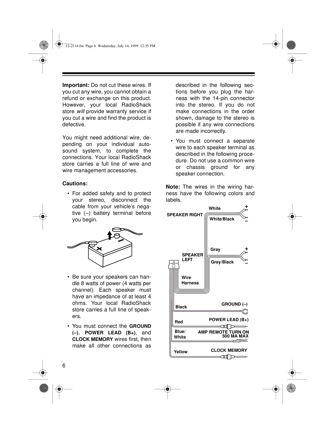
Note: The wires in the wiring har- ness have the following colors and labels.
White
SPEAKER RIGHT
White/Black
Gray
SPEAKER
• Be sure your speakers can han- |
LEFT
Wire
Gray/Black
dle 8 watts of power (4 watts per |
channel). Each speaker must |
have an impedance of at least 4 |
ohms. Your local RadioShack |
store carries a full line of speak- |
ers. |
• You must connect the GROUND |
CLOCK MEMORY wires first, then |
make all other connections as |
6
Harness
Black | GROUND |
| |
Red | POWER LEAD (B+) |
| |
Blue/ | AMP REMOTE TURN ON |
White | 500 MA MAX |
Yellow | CLOCK MEMORY |
|