Grounding
![]() WARNING
WARNING
Improper installation or alteration of grounding plug results in risk of electric shock, fire or explosion that could cause serious injury or death.
1.The 232918, 232915, 232914 require a 230 VAC, 50 Hz, 10A circuit with a grounding receptacle. The 232919 requires a 120 VAC, 50/60 Hz, 15A circuit with a grounding receptacle. The 232916, 232917 require a 100 VAC, 50 Hz, 15A circuit with a grounding receptacle. The 232910 – 232913 require 120 VAC, 60 HZ, 15A with a grounding receptacle. See Fig. 2.
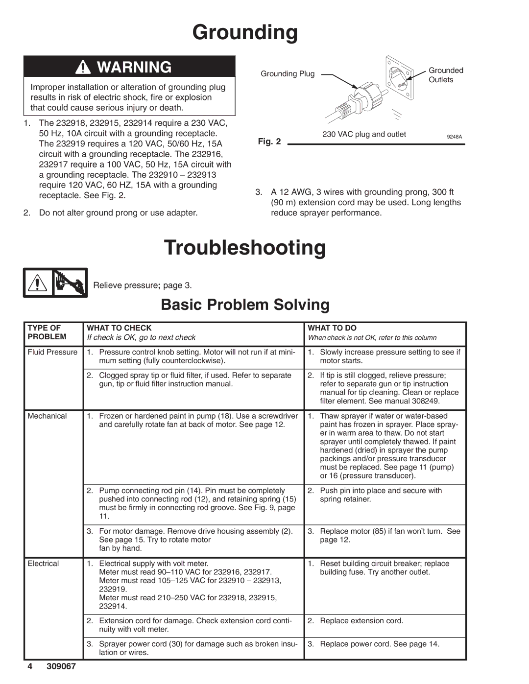
2.Do not alter ground prong or use adapter.
Grounding Plug | Grounded | |
Outlets | ||
|
Fig. 2 | 230 VAC plug and outlet | 9248A |
|
|
3.A 12 AWG, 3 wires with grounding prong, 300 ft (90 m) extension cord may be used. Long lengths reduce sprayer performance.
Troubleshooting
Relieve pressure; page 3.
Basic Problem Solving
TYPE OF | WHAT TO CHECK | WHAT TO DO | ||
PROBLEM | If check is OK, go to next check | When check is not OK, refer to this column | ||
|
|
|
|
|
Fluid Pressure | 1. | Pressure control knob setting. Motor will not run if at mini- | 1. | Slowly increase pressure setting to see if |
|
| mum setting (fully counterclockwise). |
| motor starts. |
|
|
|
|
|
| 2. | Clogged spray tip or fluid filter, if used. Refer to separate | 2. | If tip is still clogged, relieve pressure; |
|
| gun, tip or fluid filter instruction manual. |
| refer to separate gun or tip instruction |
|
|
|
| manual for tip cleaning. Clean or replace |
|
|
|
| filter element. See manual 308249. |
|
|
|
|
|
Mechanical | 1. | Frozen or hardened paint in pump (18). Use a screwdriver | 1. | Thaw sprayer if water or |
|
| and carefully rotate fan at back of motor. See page 12. |
| paint has frozen in sprayer. Place spray- |
|
|
|
| er in warm area to thaw. Do not start |
|
|
|
| sprayer until completely thawed. If paint |
|
|
|
| hardened (dried) in sprayer the pump |
|
|
|
| packings and/or pressure transducer |
|
|
|
| must be replaced. See page 11 (pump) |
|
|
|
| or 16 (pressure transducer). |
|
|
|
|
|
| 2. | Pump connecting rod pin (14). Pin must be completely | 2. | Push pin into place and secure with |
|
| pushed into connecting rod (12), and retaining spring (15) |
| spring retainer. |
|
| must be firmly in connecting rod groove. See Fig. 9, page |
|
|
|
| 11. |
|
|
|
|
|
|
|
| 3. | For motor damage. Remove drive housing assembly (2). | 3. | Replace motor (85) if fan won’t turn. See |
|
| See page 15. Try to rotate motor |
| page 12. |
|
| fan by hand. |
|
|
|
|
|
|
|
Electrical | 1. | Electrical supply with volt meter. | 1. | Reset building circuit breaker; replace |
|
| Meter must read |
| building fuse. Try another outlet. |
|
| Meter must read |
|
|
|
| 232919. |
|
|
|
| Meter must read |
|
|
|
| 232914. |
|
|
|
|
|
|
|
| 2. | Extension cord for damage. Check extension cord conti- | 2. | Replace extension cord. |
|
| nuity with volt meter. |
|
|
|
|
|
|
|
| 3. | Sprayer power cord (30) for damage such as broken insu- | 3. | Replace power cord. See page 14. |
|
| lation or wires. |
|
|
|
|
|
|
|
4309067