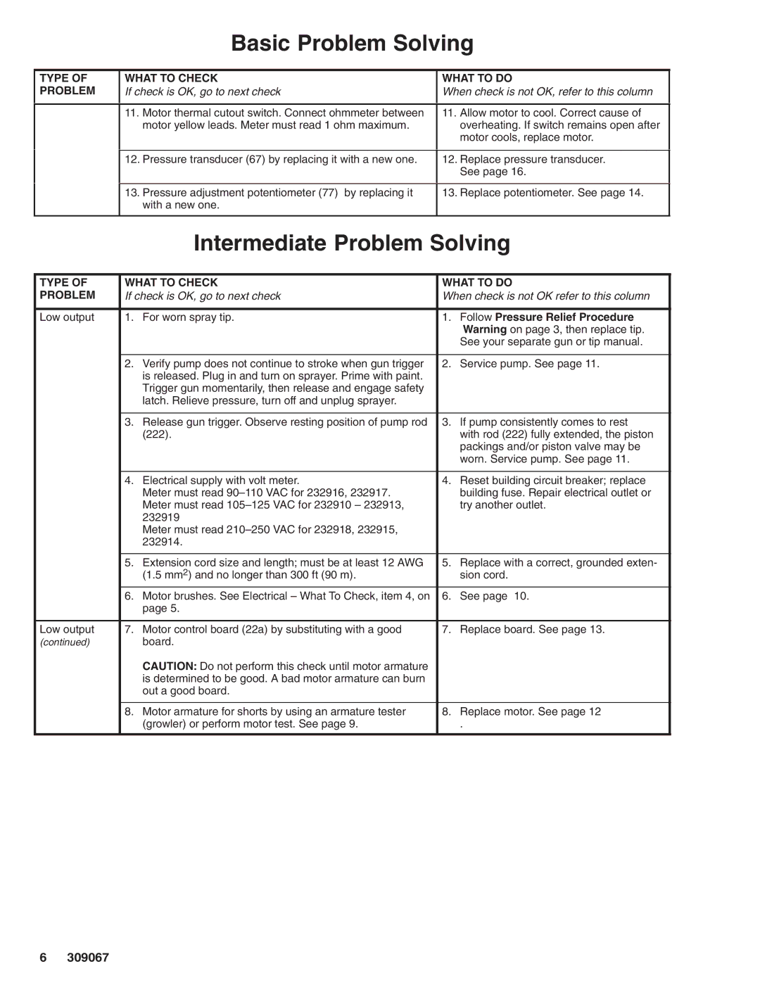
Basic Problem Solving
TYPE OF | WHAT TO CHECK | WHAT TO DO | ||
PROBLEM | If check is OK, go to next check | When check is not OK, refer to this column | ||
|
|
|
|
|
| 11. | Motor thermal cutout switch. Connect ohmmeter between | 11. | Allow motor to cool. Correct cause of |
|
| motor yellow leads. Meter must read 1 ohm maximum. |
| overheating. If switch remains open after |
|
|
|
| motor cools, replace motor. |
|
|
| ||
| 12. Pressure transducer (67) by replacing it with a new one. | 12. Replace pressure transducer. | ||
|
|
|
| See page 16. |
|
|
| ||
| 13. Pressure adjustment potentiometer (77) by replacing it | 13. Replace potentiometer. See page 14. | ||
|
| with a new one. |
|
|
|
|
|
| |
|
| Intermediate Problem Solving | ||
|
|
| ||
TYPE OF | WHAT TO CHECK | WHAT TO DO | ||
PROBLEM | If check is OK, go to next check | When check is not OK refer to this column | ||
|
|
|
|
|
Low output | 1. | For worn spray tip. | 1. | Follow Pressure Relief Procedure |
|
|
|
| Warning on page 3, then replace tip. |
|
|
|
| See your separate gun or tip manual. |
|
|
|
|
|
| 2. | Verify pump does not continue to stroke when gun trigger | 2. | Service pump. See page 11. |
|
| is released. Plug in and turn on sprayer. Prime with paint. |
|
|
|
| Trigger gun momentarily, then release and engage safety |
|
|
|
| latch. Relieve pressure, turn off and unplug sprayer. |
|
|
|
|
|
|
|
| 3. | Release gun trigger. Observe resting position of pump rod | 3. | If pump consistently comes to rest |
|
| (222). |
| with rod (222) fully extended, the piston |
|
|
|
| packings and/or piston valve may be |
|
|
|
| worn. Service pump. See page 11. |
|
|
|
|
|
| 4. | Electrical supply with volt meter. | 4. | Reset building circuit breaker; replace |
|
| Meter must read |
| building fuse. Repair electrical outlet or |
|
| Meter must read |
| try another outlet. |
|
| 232919 |
|
|
|
| Meter must read |
|
|
|
| 232914. |
|
|
|
|
|
|
|
| 5. | Extension cord size and length; must be at least 12 AWG | 5. | Replace with a correct, grounded exten- |
|
| (1.5 mm2) and no longer than 300 ft (90 m). |
| sion cord. |
| 6. | Motor brushes. See Electrical – What To Check, item 4, on | 6. | See page 10. |
|
| page 5. |
|
|
|
|
|
|
|
Low output | 7. | Motor control board (22a) by substituting with a good | 7. | Replace board. See page 13. |
(continued) |
| board. |
|
|
|
| CAUTION: Do not perform this check until motor armature |
|
|
|
| is determined to be good. A bad motor armature can burn |
|
|
|
| out a good board. |
|
|
|
|
|
|
|
| 8. | Motor armature for shorts by using an armature tester | 8. | Replace motor. See page 12 |
|
| (growler) or perform motor test. See page 9. |
| . |
|
|
|
|
|
6309067
