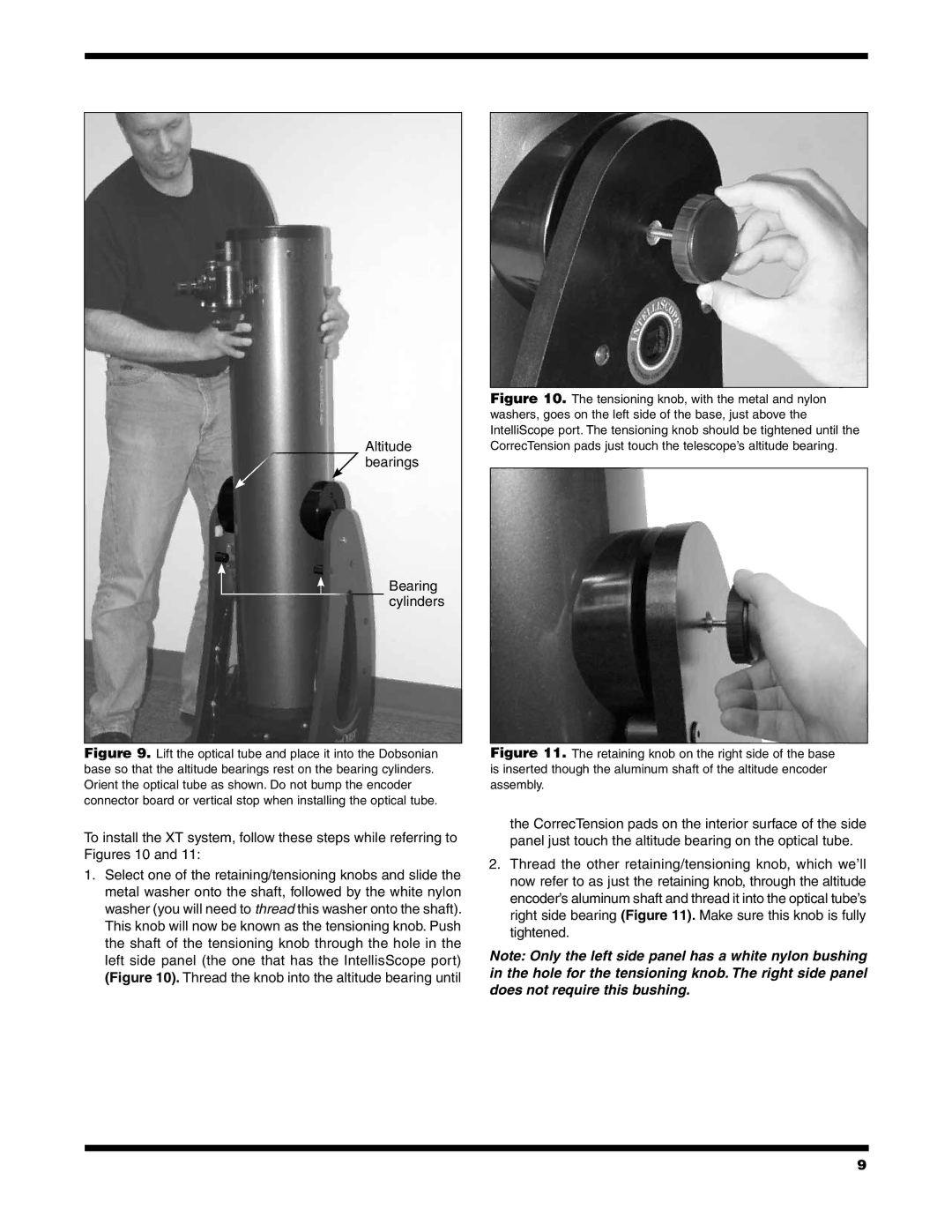
10019 XT10i, 10018 XT8i, 10020 XT12i, 10026 XT6i specifications
The Orion XT series of telescopes, including the XT12i, XT8i, XT6i, and XT10i, are highly regarded for their quality and performance, making them popular choices among astronomy enthusiasts. Each model in the XT line features a Dobsonian design, renowned for its simplicity and ease of use, allowing users to enjoy stargazing without the complexities associated with other types of telescopes.Starting with the Orion XT12i, this model boasts a 12-inch aperture that delivers exceptional light-gathering power, ideal for deep-sky observations. Equipped with the IntelliScope computer navigation system, users can enjoy the convenience of locating over 14,000 celestial objects with ease. The oversized 2-inch focuser accommodates a range of eyepieces and accessories, while the solid, sturdy base ensures stability during observation.
Next is the Orion XT10i, featuring a 10-inch aperture designed for delivering stunning views of galaxies, nebulae, and star clusters. Like its larger counterpart, the XT10i also comes with the IntelliScope system, allowing for simple object location. Its compact design makes it an ideal choice for both backyard astronomy and portable stargazing trips. The XT10i includes a rich set of accessories, including a 1.25-inch eyepiece, to enhance the observing experience.
The Orion XT8i brings a 8-inch aperture to those seeking a balance between performance and portability. This telescope offers impressive light-gathering capabilities while remaining lightweight enough for easy transport. The IntelliScope feature enables users to navigate easily between celestial objects. It is an excellent choice for both beginners and experienced users looking for a versatile telescope.
Finally, the Orion XT6i features a 6-inch aperture, making it an optimal choice for those new to astronomy. Despite its smaller size, the XT6i still offers excellent views of the night sky and is highly portable. With the IntelliScope system, users can quickly find and explore various celestial objects. Its user-friendly design and setup make it a perfect introduction to the world of astronomy for novices.
In summary, the Orion XT series of telescopes presents a diverse range of options suitable for astronomers of all experience levels. They combine innovative technologies like the IntelliScope navigation system with solid construction and impressive optics, ensuring memorable astronomical experiences. Whether you're delving into deep-sky exploration or enjoying casual stargazing, the XT line has a model that fits your needs.

