BioOptix™ 10
Appendix B Fluid Path Diagrams
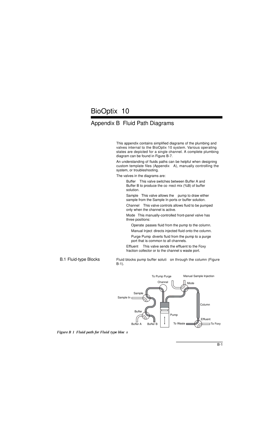
B.1 Fluid-type Blocks
This appendix contains simplified diagrams of the plumbing and valves internal to the BioOptix 10 system. Various operating states are depicted for a single channel. A complete plumbing diagram can be found in Figure
An understanding of fluids paths can be helpful when designing custom template files (Appendix A), manually controlling the system, or troubleshooting.
The valves in the diagrams are:
•
•
•
•
❍
❍Manual
❍Purge
•
Fluid blocks pump buffer solution through the column (Figure
| To Pump Purge | Manual Sample Injection | |
| Channel |
| Mode |
|
|
| |
Sample |
|
|
|
Sample In |
|
|
|
|
|
| Column |
Buffer |
|
|
|
| Pump |
| |
|
|
| Effluent |
Buffer A | Buffer B | To Waste | To Foxy |