BioOptix™ 10
Section 2 Installation
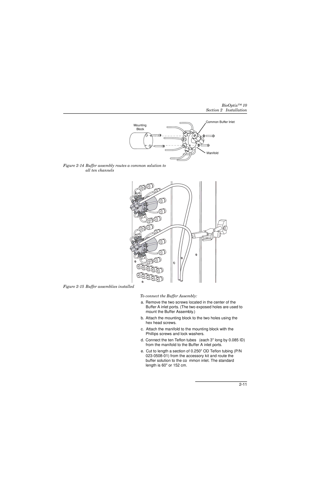
Common Buffer Inlet
Mounting
Block
 Manifold
Figure 2-14 Buffer assembly routes a common solution to all ten channels
Figure 2-15 Buffer assemblies installed
To connect the Buffer Assembly:
a.Remove the two screws located in the center of the Buffer A inlet ports. (The two exposed holes are used to mount the Buffer Assembly.)
b.Attach the mounting block to the two holes using the hex head screws.
c.Attach the manifold to the mounting block with the Phillips screws and lock washers.
d.Connect the ten Teflon tubes (each 3" long by 0.085 ID) from the manifold to the Buffer A inlet ports.
e.Cut to length a section of 0.250" OD Teflon tubing (P/N