BioOptix™ 10
Section 2 Installation
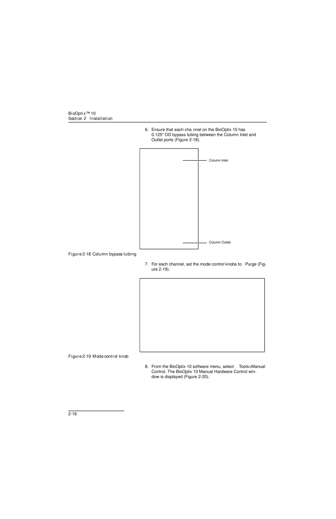
6.Ensure that each channel on the BioOptix 10 has 0.125" OD bypass tubing between the Column Inlet and Outlet ports (Figure
Column Inlet
Column Outlet
Figure 2-18 Column bypass tubing
7.For each channel, set the mode control knobs to Purge (Fig- ure
Figure 2-19 Mode control knob
8.From the BioOptix 10 software menu, select Tools>Manual Control. The BioOptix 10 Manual Hardware Control win- dow is displayed (Figure