BioOptix™ 10
Section 1 Introduction
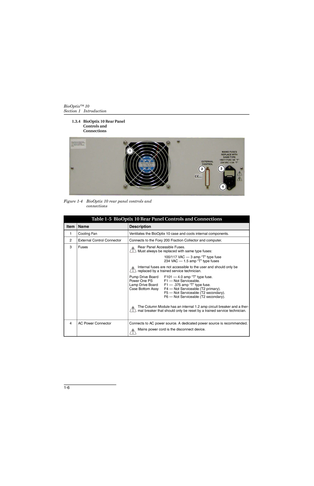
1.3.4BioOptix 10 Rear Panel Controls and Connections
![]() 1
1 ![]()
2 | 3 |
![]() 4
4 ![]()
Figure 1-4 BioOptix 10 rear panel controls and connections
Table 1-5 BioOptix 10 Rear Panel Controls and Connections
Item | Name | Description |
|
|
1 | Cooling Fan | Ventilates the BioOptix 10 case and cools internal components. | ||
|
|
| ||
2 | External Control Connector | Connects to the Foxy 200 Fraction Collector and computer. | ||
|
|
| ||
3 | Fuses | Rear Panel Accessible Fuses. | ||
|
| Must always be replaced with same type fuses: | ||
|
|
| 100/117 VAC — 3 amp “T” type fuse | |
|
|
| 234 VAC — 1.5 amp “T” type fuses | |
|
| Internal fuses are not accessible to the user and should only be | ||
|
| replaced by a trained service technician. | ||
|
| Pump Drive Board | F101 — 4.0 amp “T” type fuse. | |
|
| Power One PS | F1 | — Not Serviceable. |
|
| Lamp Drive Board | F1 | |
|
| Case Bottom Assy | F4 | — Not Serviceable (T2 primary). |
|
|
| F5 | — Not Serviceable (T2 secondary). |
|
|
| F6 | — Not Serviceable (T2 secondary). |
|
| The Column Module has an internal 1.2 amp circuit breaker and a ther- | ||
|
| mal breaker that should only be reset by a trained service technician. | ||
|
|
| ||
4 | AC Power Connector | Connects to AC power source. A dedicated power source is recommended. | ||
![]() Mains power cord is the disconnect device.
Mains power cord is the disconnect device.