BioOptix™ 10
Section 2 Installation
Buffer B – To form gradient buffers during purification, connect Buffer B solution(s) to these ten inlet ports. Perform the steps described in Buffer A above to complete these fluid connections.
Sample In – The ferrules on these inlet ports accept the 0.063" OD tubing. The accessory kit contains Teflon tubing of this size in five different colors. Cut the tubing to length (standard length is 36" or 91 cm), insert one end into a Sample In port, and route the other end to the sample container.
![]()
![]()
![]()
![]()
![]() Note
Note
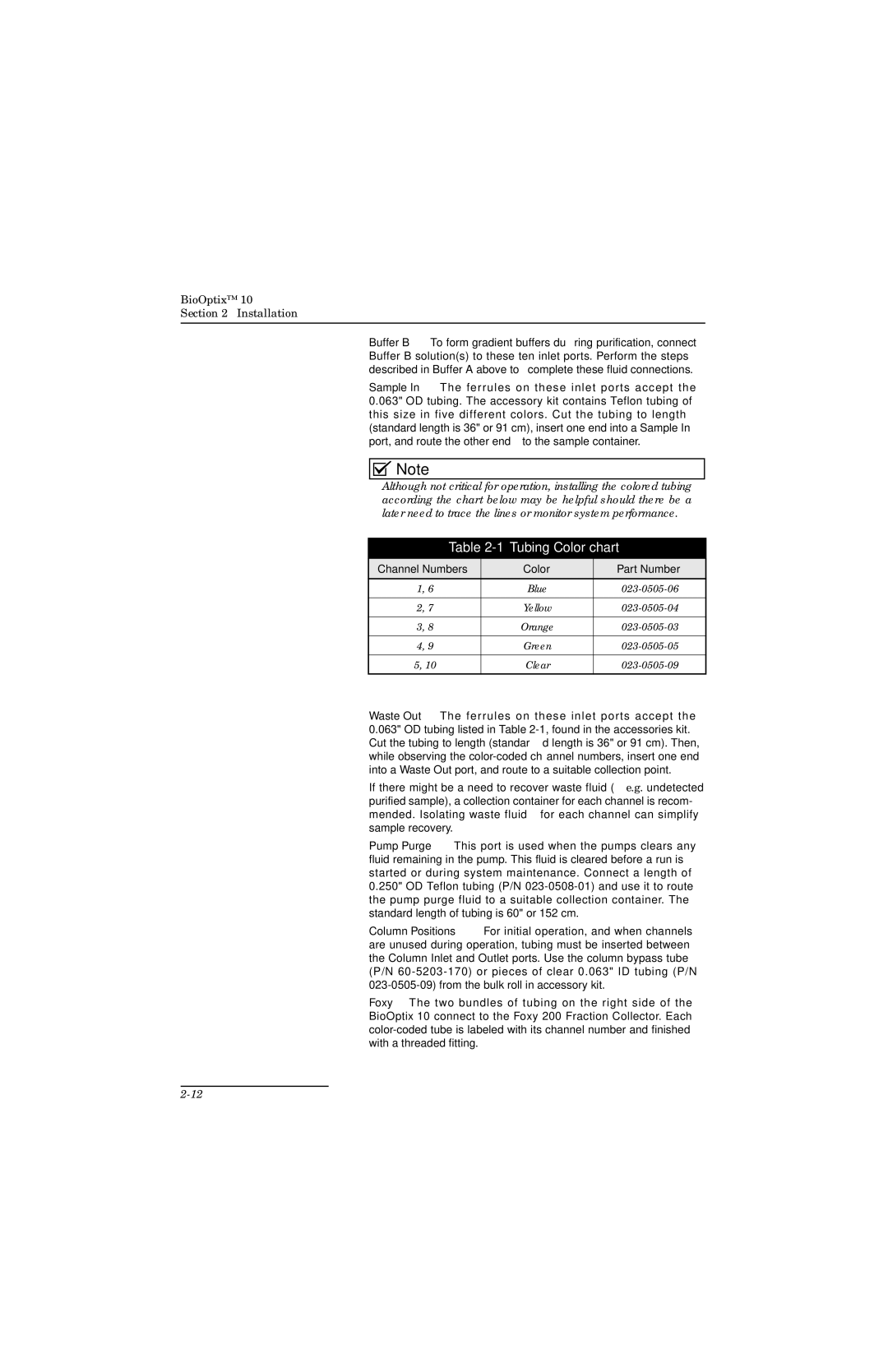
Although not critical for operation, installing the colored tubing according the chart below may be helpful should there be a later need to trace the lines or monitor system performance.
Table 2-1 Tubing Color chart
Channel Numbers | Color | Part Number |
1, 6 | Blue | |
|
|
|
2, 7 | Yellow | |
|
|
|
3, 8 | Orange | |
|
|
|
4, 9 | Green | |
|
|
|
5, 10 | Clear | |
|
|
|
Waste Out – The ferrules on these inlet ports accept the 0.063" OD tubing listed in Table
If there might be a need to recover waste fluid (e.g. undetected purified sample), a collection container for each channel is recom- mended. Isolating waste fluid for each channel can simplify sample recovery.
Pump Purge – This port is used when the pumps clears any fluid remaining in the pump. This fluid is cleared before a run is started or during system maintenance. Connect a length of 0.250" OD Teflon tubing (P/N
Column Positions – For initial operation, and when channels are unused during operation, tubing must be inserted between the Column Inlet and Outlet ports. Use the column bypass tube (P/N
Foxy – The two bundles of tubing on the right side of the BioOptix 10 connect to the Foxy 200 Fraction Collector. Each