BioOptix™ 10
Section 2 Installation
12.Ensure the Power Switch is in the Off (“0”) position. Then, connect the AC power cord to the back of the Pump Mod- ule. Connect the other end of the power cord to an outlet meeting the electrical requirements listed on the serial number label.
13.Locate the Serial “Y” cable, P/N
The BioOptix 10 may now be positioned on the bench as shown in Figure
![]() WARNING
WARNING
The system is heavy. Use a two-person lift to prevent injury.
| 14. | Insert the ten column clamps into the BioOptix 10. Secure |
|
| the clamps by tighten the thumbscrews against the stain- |
|
| less steel shafts (Figure |
2.2.4 Assembling the | 1. | Refer to section 2 of the Foxy 200 |
Foxy 200 |
| instruction manual. Unpack the Foxy 200 and assemble |
|
| the arm. |
|
|
|
|
| Note |
| To prevent damage to the ground wire on the fraction collector | |
| arm, attach the | |
| ceeding with the arm assembly instructions. | |
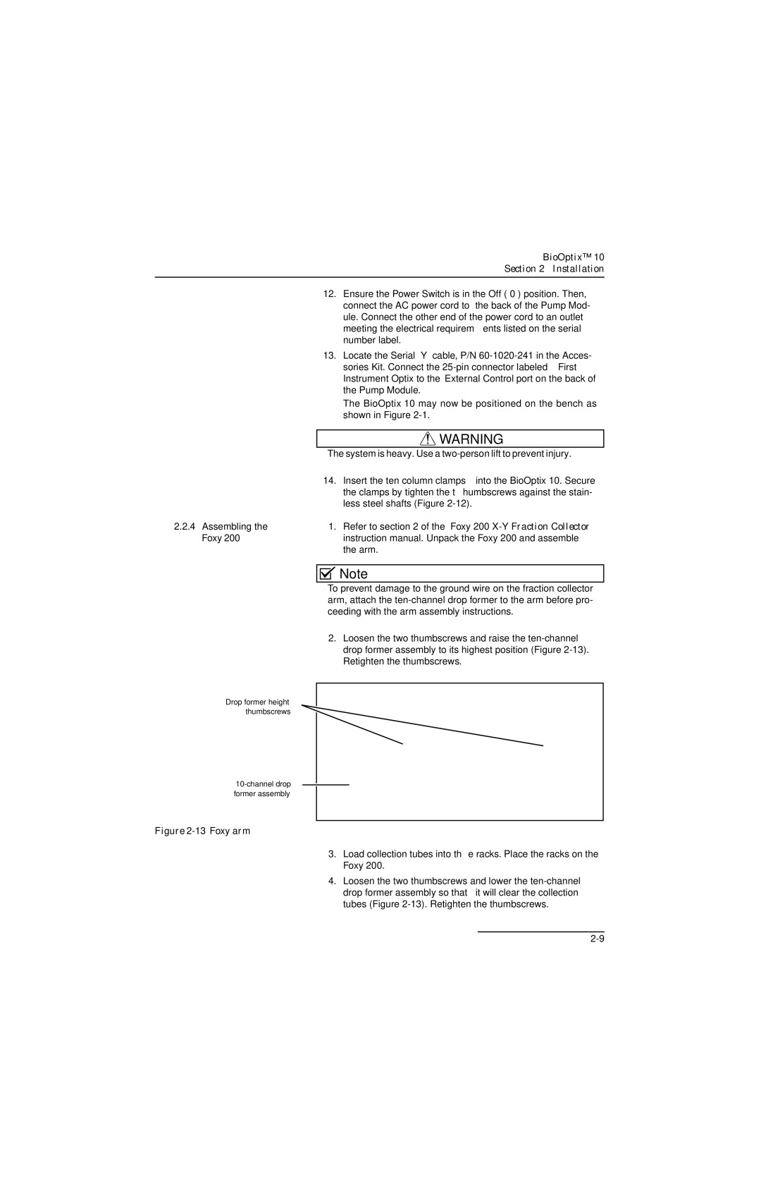
| 2. | Loosen the two thumbscrews and raise the |
|
| drop former assembly to its highest position (Figure |
|
| Retighten the thumbscrews. |
Drop former height thumbscrews
Figure 2-13 Foxy arm
3.Load collection tubes into the racks. Place the racks on the Foxy 200.
4.Loosen the two thumbscrews and lower the