BioOptix™ 10
Section 2 Installation
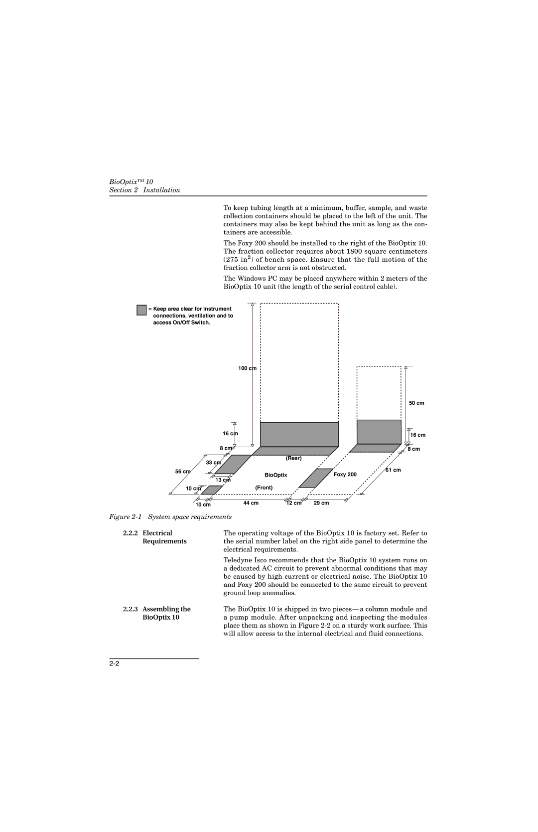
To keep tubing length at a minimum, buffer, sample, and waste collection containers should be placed to the left of the unit. The containers may also be kept behind the unit as long as the con- tainers are accessible.
The Foxy 200 should be installed to the right of the BioOptix 10. The fraction collector requires about 1800 square centimeters (275 in2) of bench space. Ensure that the full motion of the fraction collector arm is not obstructed.
The Windows PC may be placed anywhere within 2 meters of the
BioOptix 10 unit (the length of the serial control cable).
=Keep area clear for instrument connections, ventilation and to access On/Off Switch.
100 cm
16 cm
8 cm![]()
(Rear)
33 cm
50 cm
16cm
8 cm
56 cm |
| BioOptix | 61 cm |
| 13 cm | Foxy 200 | |
|
|
| |
10 cm | (Front) |
| |
10 cm | 44 cm | 12 cm | 29 cm |
|
|
| |
Figure 2-1 System space requirements
2.2.2 | Electrical | The operating voltage of the BioOptix 10 is factory set. Refer to |
| Requirements | the serial number label on the right side panel to determine the |
|
| electrical requirements. |
|
| Teledyne Isco recommends that the BioOptix 10 system runs on |
|
| a dedicated AC circuit to prevent abnormal conditions that may |
|
| be caused by high current or electrical noise. The BioOptix 10 |
|
| and Foxy 200 should be connected to the same circuit to prevent |
|
| ground loop anomalies. |
2.2.3 | Assembling the | The BioOptix 10 is shipped in two |
| BioOptix 10 | a pump module. After unpacking and inspecting the modules |
|
| place them as shown in Figure |
|
| will allow access to the internal electrical and fluid connections. |