BioOptix™ 10
Section 1 Introduction
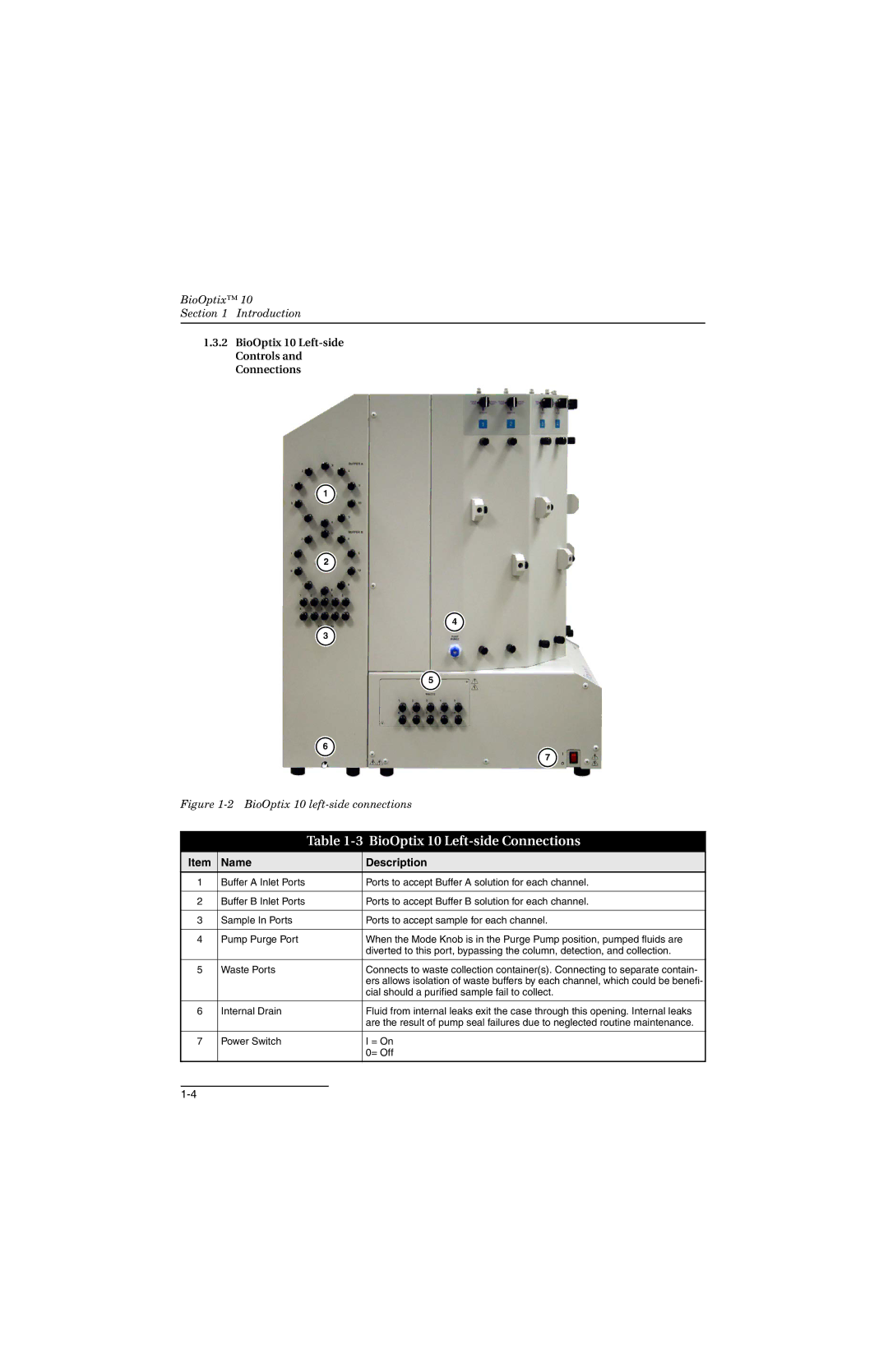
1.3.2BioOptix 10 Left-side Controls and Connections
![]() 1
1 ![]()
![]() 2
2 ![]()
![]() 4
4 ![]()
3 ![]()
![]() 5
5 ![]()
|
| 6 |
|
|
| 7 | |
Figure | |||
|
|
|
|
|
| Table | |
|
|
|
|
Item | Name |
| Description |
1 | Buffer A Inlet Ports |
| Ports to accept Buffer A solution for each channel. |
|
|
|
|
2 | Buffer B Inlet Ports |
| Ports to accept Buffer B solution for each channel. |
|
|
|
|
3 | Sample In Ports |
| Ports to accept sample for each channel. |
|
|
|
|
4 | Pump Purge Port |
| When the Mode Knob is in the Purge Pump position, pumped fluids are |
|
|
| diverted to this port, bypassing the column, detection, and collection. |
|
|
|
|
5 | Waste Ports |
| Connects to waste collection container(s). Connecting to separate contain- |
|
|
| ers allows isolation of waste buffers by each channel, which could be benefi- |
|
|
| cial should a purified sample fail to collect. |
|
|
|
|
6 | Internal Drain |
| Fluid from internal leaks exit the case through this opening. Internal leaks |
|
|
| are the result of pump seal failures due to neglected routine maintenance. |
|
|
|
|
7 | Power Switch |
| I = On |
|
|
| 0= Off |
|
|
|
|