CABLE DIAGRAMS
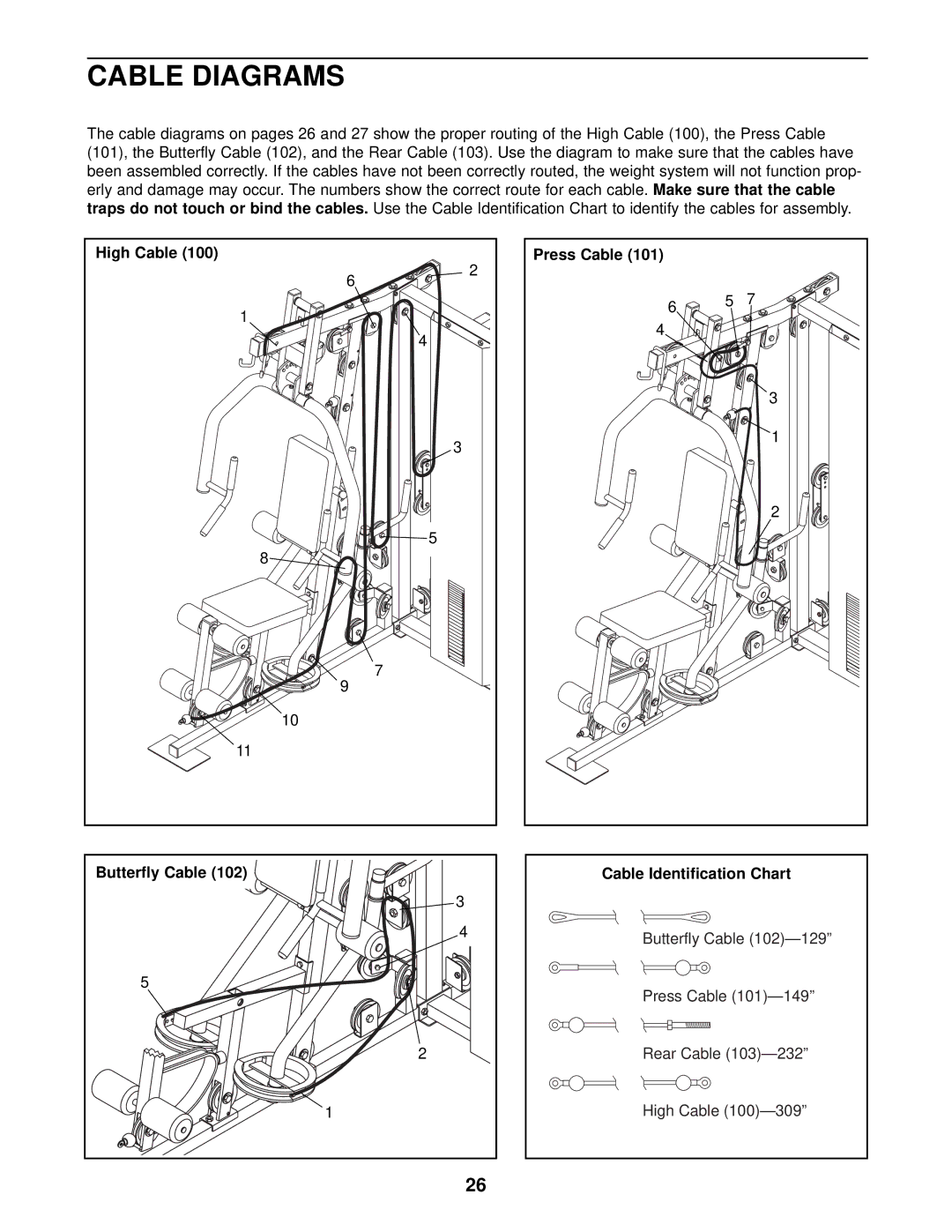
The cable diagrams on pages 26 and 27 show the proper routing of the High Cable (100), the Press Cable (101), the Butterfly Cable (102), and the Rear Cable (103). Use the diagram to make sure that the cables have been assembled correctly. If the cables have not been correctly routed, the weight system will not function prop- erly and damage may occur. The numbers show the correct route for each cable. Make sure that the cable traps do not touch or bind the cables. Use the Cable Identification Chart to identify the cables for assembly.
High Cable (100) |
2 |
6 |
1 |
4 |
3 |
5 |
8 |
7 |
9 |
10 |
11 |
Butterfly Cable (102) |
3 |
4 |
5 |
2 |
1 |
26 |
Press Cable (101) |
|
|
6 | 5 | 7 |
|
| |
4 |
|
|
|
| 3 |
|
| 1 |
|
| 2 |
Cable Identification Chart
Butterfly Cable
Press Cable
Rear Cable
High Cable