DESCRIPTION OF THE PARTS
EXTERNAL PARTS
1.Flash Head | Panel | 3.AF | Auxiliary Light | 4.Bounce Angle; | Up and | Down | ||
5.Bounce Angle; Right and Left | 6.Bounce Lock and Release Button; Up and Down | 7.Swivel | Lock | |||||
and Release Button; Right and Left | 8.LCD Panel 9.Battery Cover | 10.Shoe Ring | 11.Shoe |
| ||||
CONTROLS |
|
|
|
|
|
|
|
|
12.MODE Button | 13.<SEL> SELECT Button | 14.< + > Increment Button | 15.< - > Decrement Button | |||||
16.ZOOM Button | 17.TEST Button 18.LIGHT Button 19.Ready Light | 20.Power Switch |
| |||||
ABOUT THE BATTERY
This flash unit uses four “AA” type Alkaline dry cell batteries,
■To assure proper electrical contact, clean the battery terminals before installing the batteries.
■NiCad batteries do not have standardized contacts. If you use NiCad batteries, please confirm that the battery contacts touch the battery compartment properly.
■To prevent battery explosion, leakage or overheating, use four new AA batteries of the same type and brand. Do not mix the type or new and used batteries.
■Do not disassemble or
■When the flash will not be used for an extended period of time, remove the batteries from the flash to avoid the possibility of damage from leakage.
■Battery performance decreases at low temperatures. Keep batteries insulated when using the flash in cold weather.
■As with any flash, it is recommended you carry spare batteries when on a long trip or when photographing outdoors in cold weather.
BATTERY LOADING
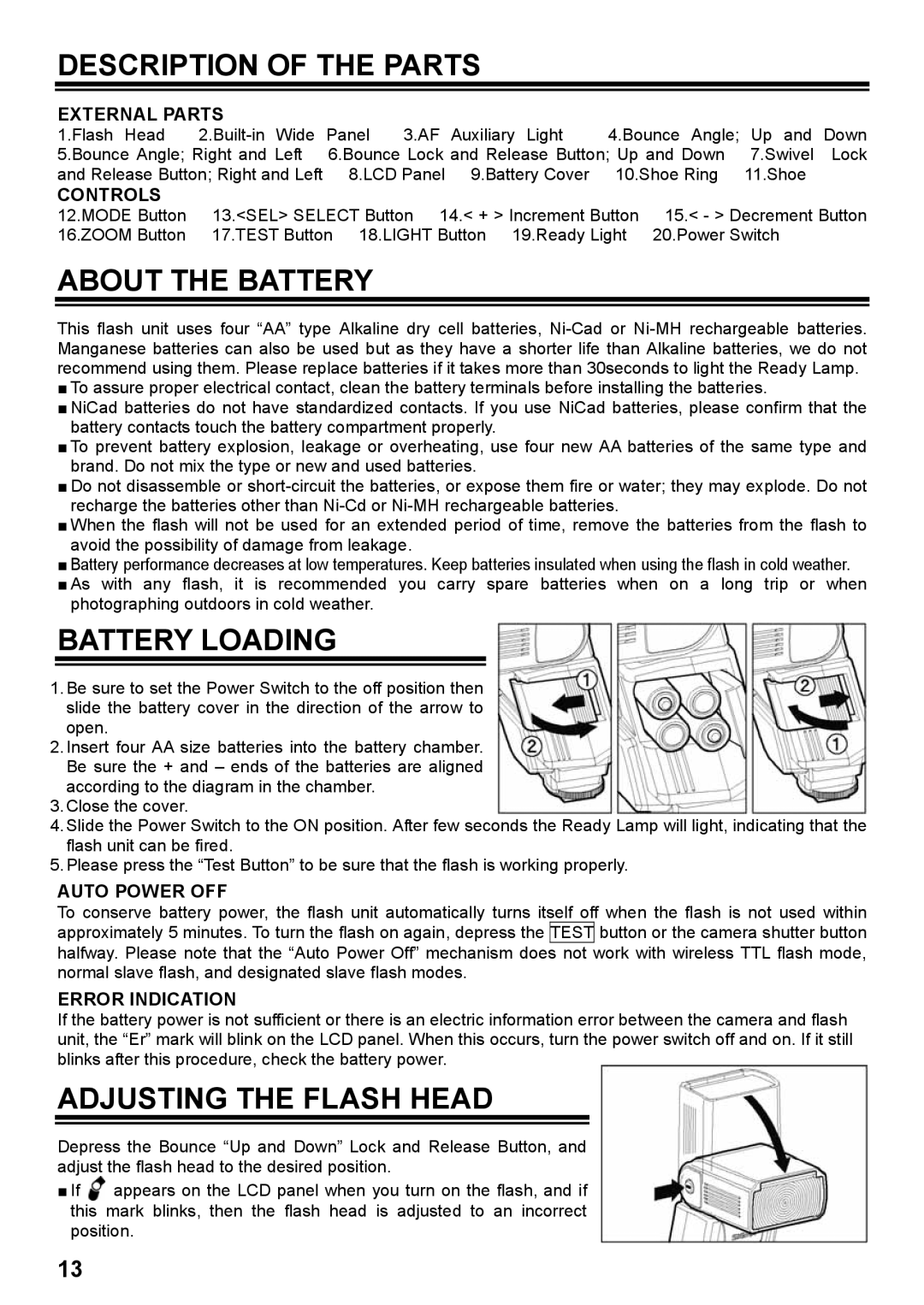
1.Be sure to set the Power Switch to the off position then slide the battery cover in the direction of the arrow to open.
2.Insert four AA size batteries into the battery chamber. Be sure the + and – ends of the batteries are aligned according to the diagram in the chamber.
3.Close the cover.
4.Slide the Power Switch to the ON position. After few seconds the Ready Lamp will light, indicating that the
flash unit can be fired.
5.Please press the “Test Button” to be sure that the flash is working properly.
AUTO POWER OFF
To conserve battery power, the flash unit automatically turns itself off when the flash is not used within approximately 5 minutes. To turn the flash on again, depress the TEST button or the camera shutter button halfway. Please note that the “Auto Power Off” mechanism does not work with wireless TTL flash mode, normal slave flash, and designated slave flash modes.
ERROR INDICATION
If the battery power is not sufficient or there is an electric information error between the camera and flash unit, the “Er” mark will blink on the LCD panel. When this occurs, turn the power switch off and on. If it still blinks after this procedure, check the battery power.
ADJUSTING THE FLASH HEAD
Depress the Bounce “Up and Down” Lock and Release Button, and adjust the flash head to the desired position.
■If ![]() appears on the LCD panel when you turn on the flash, and if this mark blinks, then the flash head is adjusted to an incorrect position.
appears on the LCD panel when you turn on the flash, and if this mark blinks, then the flash head is adjusted to an incorrect position.
13