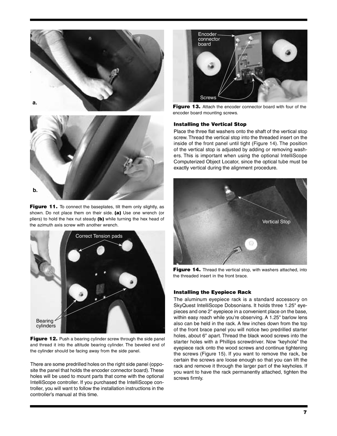
Encoder connector board ![]()
a.
Screws
Figure 13. Attach the encoder connector board with four of the encoder board mounting screws.
Installing the Vertical Stop
Place the three flat washers onto the shaft of the vertical stop screw. Thread the vertical stop into the threaded insert on the inside of the front panel until tight (Figure 14). The position of the vertical stop is adjusted by adding or removing wash- ers. This is important when using the optional IntelliScope Computerized Object Locator, since the optical tube must be exactly vertical during the alignment procedure.
b.
Figure 11. To connect the baseplates, tilt them only slightly, as shown. Do not place them on their side. (a) Use one wrench (or pliers) to hold the hex nut steady (b) while turning the hex head of the azimuth axis screw with another wrench.
Correct Tension pads
Bearing ![]() cylinders
cylinders
Figure 12. Push a bearing cylinder screw through the side panel and thread it into the altitude bearing cylinder. The beveled end of the cylinder should be facing away from the side panel.
There are some predrilled holes on the right side panel (oppo- site the panel that holds the encoder connector board). These holes will be used to mount parts that come with the optional IntelliScope controller. If you purchased the IntelliScope con- troller, you will want to follow the installation instructions in the controller’s manual at this time.
Vertical Stop
Figure 14. Thread the vertical stop, with washers attached, into the threaded insert in the front brace.
Installing the Eyepiece Rack
The aluminum eyepiece rack is a standard accessory on SkyQuest IntelliScope Dobsonians. It holds three 1.25" eye- pieces and one 2" eyepiece in a convenient place on the base, within easy reach while you’re observing. A 1.25" barlow lens also can be held in the rack. A few inches down from the top of the front brace panel you will notice two predrilled starter holes, about 6" apart. Thread the black wood screws into the starter holes with a Phillips screwdriver. Now “keyhole” the eyepiece rack onto the wood screws and continue tightening the screws (Figure 15). If you want to remove the rack, be certain the screws are loose enough so that you can lift the rack and remove it through the larger part of the keyholes. If you want to have the rack permanently attached, tighten the screws firmly.
7