C
B

 KL
KL


 M D
M D 

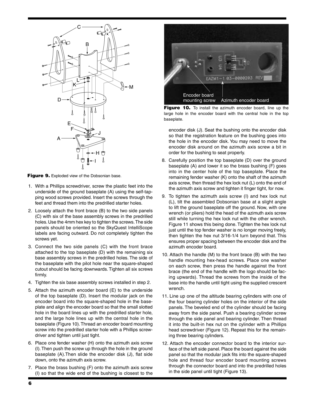
Encoder board
mounting screw Azimuth encoder board
Figure 10. To install the azimuth encoder board, line up the large hole in the encoder board with the central hole in the top baseplate.
E
F
A
![]() J
J
encoder disk (J). Seat the bushing onto the encoder disk so that the registration feature on the bushing goes into the hole in the encoder disk. You may need to move the encoder disk around on the azimuth axis screw a bit in
![]()
![]() H
H ![]()
![]()
![]() I
I
Figure 9. Exploded view of the Dobsonian base.
1.With a Phillips screwdriver, screw the plastic feet into the underside of the ground baseplate (A) using the self-tap- ping wood screws provided. Insert the screws through the feet and thread them into the predrilled starter holes.
2.Loosely attach the front brace (B) to the two side panels
(C)with six of the base assembly screws in the predrilled holes. Use the 4mm hex key to tighten the screws.The side panels should be oriented so the SkyQuest IntelliScope labels are facing outward. Do not completely tighten the screws yet.
3.Connect the two side panels (C) with the front brace attached to the top baseplate (D) with the remaining six base assembly screws in the predrilled holes. The side of the baseplate with the pilot hole near the
4.Tighten the six base assembly screws installed in step 2.
5.Attach the azimuth encoder board (E) to the underside of the top baseplate (D). Insert the modular jack on the encoder board into the
6.Place one fender washer (H) onto the azimuth axis screw
(I).Then push the screw up through the hole in the ground baseplate (A).Then slide the encoder disk (J), flat side down, onto the azimuth axis screw.
7.Place the brass bushing (F) onto the azimuth axis screw
(I)so that the wide end of the bushing is closest to the
order for the bushing to seat properly.
8.Carefully position the top baseplate (D) over the ground baseplate (A) and lower it so the brass bushing (F) goes into in the center hole of the top baseplate. Place the remaining fender washer (K) onto the shaft of the azimuth axis screw, then thread the hex lock nut (L) onto the end of the azimuth axis screw and tighten it finger tight, for now.
9.To tighten the azimuth axis screw (I) and hex lock nut (L), tilt the assembled Dobsonian base at a slight angle to lift the ground baseplate off the ground. Now, with one wrench (or pliers) hold the head of the azimuth axis screw still while turning the hex lock nut with the other wrench. Figure 11 shows this being done. Tighten the hex lock nut just until the top fender washer is no longer moving freely, then tighten the hex nut
10.Attach the handle (M) to the front brace (B) with the two handle mounting
11.Line up one of the altitude bearing cylinders with one of the four bearing cylinder holes on the interior of the side panels. The beveled end of the cylinder should be facing away from the side panel. Push a bearing cylinder screw through the side panel and bearing cylinder. Then thread it into the
12.Attach the encoder connector board to the interior sur- face of the left side panel. Place the board against the side panel so that the modular jack fits into the
6