Figure 15. Using the two supplied screws, install the aluminum eyepiece rack in the predrilled holes near the top of the front baseplate.
Placing the Optical Tube on the Dobsonian Base
Lift the optical tube and gently place it into the Dobsonian base so that the altitude bearings on either side of the tube rest on the bearing cylinders. Be careful when doing this, as the optical tube is somewhat heavy and unwieldy. Orient the optical tube as shown in Figure 16. Make certain that the optical tube does not get hung up on the vertical stop or the CorrecTension pads as you put it in place. Also make cer- tain not to angle the tube so its altitude bearings can strike the encoder connector board and potentially damage it. Once on the bearing cylinders, the tube should pivot freely up and down with gentle hand pressure. Note that the tube will not yet be properly balanced, since the eyepiece and finder scope are not in place, and the CorrecTension system has not been installed.
Installing the CorrecTension Friction
Optimization System
An exciting feature of the SkyQuest IntelliScope Dobsonian is the redesigned CorrecTension (XT) system. Because of their relatively light weight, smaller Dobsonians (under 16") have always been plagued by insufficient friction on the altitude bearing surfaces. As a result, such telescopes move up and down much too freely.This causes problems when the observ- er tries to accurately center and track an object for viewing, especially at higher powers. Also, the telescope becomes very sensitive to balance, requiring additional equipment such as counterweight systems or springs to compensate.
SkyQuest Intelliscope Dobsonians employ a simple yet effec- tive remedy for the friction problem that obviates the need for such cumbersome countermeasures. CorrecTension Friction Optimization utilizes a simple “disc brake” to apply the correct level of tension to the altitude bearings. With the XT system, you can change eyepieces or add a barlow lens without hav- ing to tediously adjust the telescope’s balance as you would with other Dobsonians. The altitude friction can be made equal to the azimuth friction, ensuring optimal performance.
To install the XT system, follow these steps while referring to Figures 17 and 18:
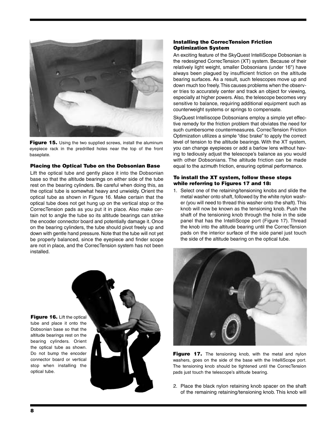
1.Select one of the retaining/tensioning knobs and slide the metal washer onto shaft, followed by the white nylon wash- er (you will need to thread this washer onto the shaft). This knob will now be known as the tensioning knob. Push the shaft of the tensioning knob through the hole in the side panel that has the IntelliScope port (Figure 17). Thread the knob into the altitude bearing until the CorrecTension pads on the interior surface of the side panel just touch the side of the altitude bearing on the optical tube.
Figure 16. Lift the optical tube and place it onto the Dobsonian base so that the altitude bearings rest on the bearing cylinders. Orient the optical tube as shown. Do not bump the encoder connector board or vertical stop when installing the optical tube.
Figure 17. The tensioning knob, with the metal and nylon washers, goes on the side of the base with the IntelliScope port. The tensioning knob should be tightened until the CorrecTension pads just touch the telescope’s altitude bearing.
2.Place the black nylon retaining knob spacer on the shaft of the remaining retaining/tensioning knob. This knob will
8