Front Panel Header
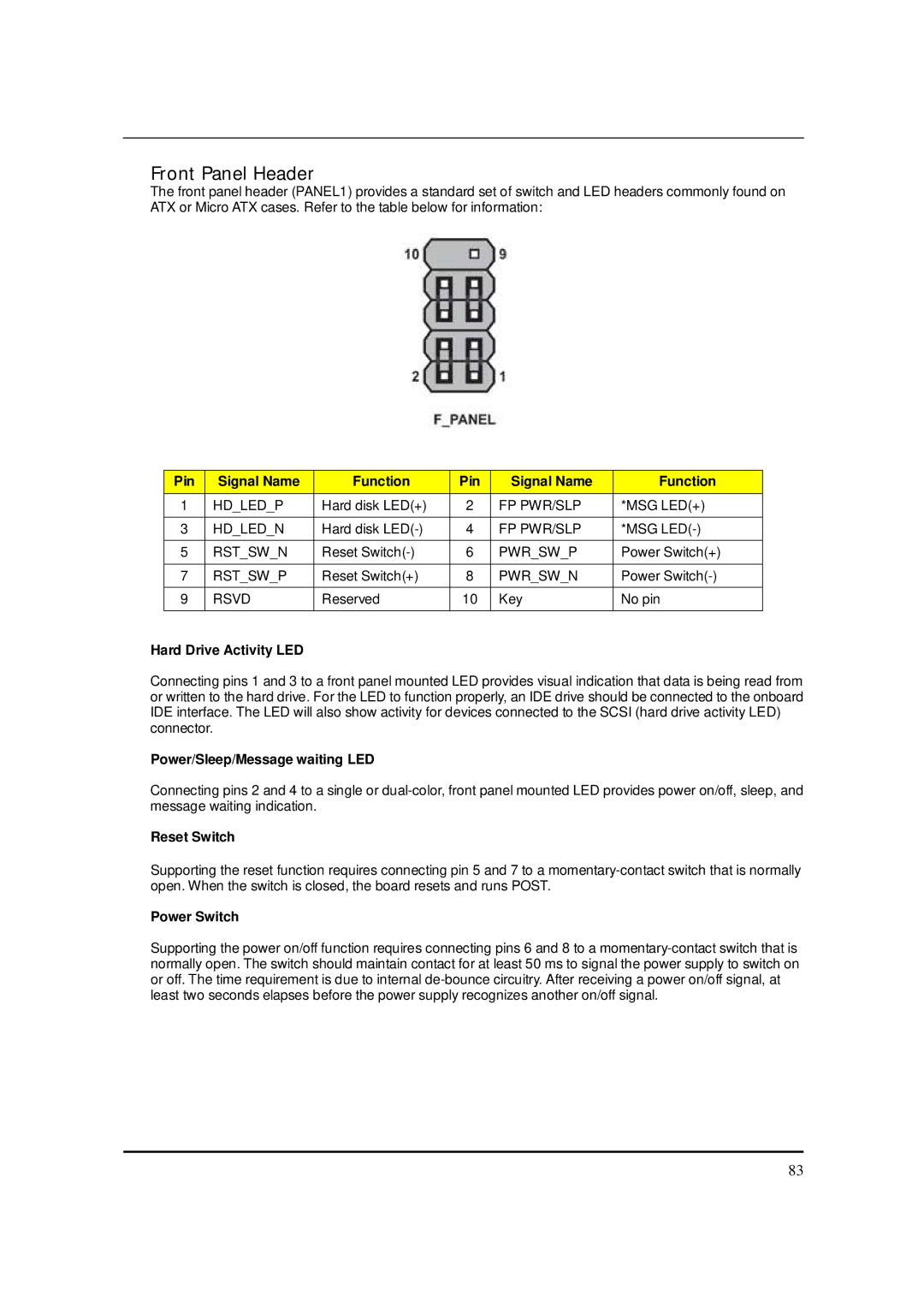
The front panel header (PANEL1) provides a standard set of switch and LED headers commonly found on ATX or Micro ATX cases. Refer to the table below for information:
Pin | Signal Name | Function | Pin | Signal Name | Function |
1 | HD_LED_P | Hard disk LED(+) | 2 | FP PWR/SLP | *MSG LED(+) |
|
|
|
|
|
|
3 | HD_LED_N | Hard disk | 4 | FP PWR/SLP | *MSG |
|
|
|
|
|
|
5 | RST_SW_N | Reset | 6 | PWR_SW_P | Power Switch(+) |
|
|
|
|
|
|
7 | RST_SW_P | Reset Switch(+) | 8 | PWR_SW_N | Power |
|
|
|
|
|
|
9 | RSVD | Reserved | 10 | Key | No pin |
|
|
|
|
|
|
Hard Drive Activity LED
Connecting pins 1 and 3 to a front panel mounted LED provides visual indication that data is being read from or written to the hard drive. For the LED to function properly, an IDE drive should be connected to the onboard IDE interface. The LED will also show activity for devices connected to the SCSI (hard drive activity LED) connector.
Power/Sleep/Message waiting LED
Connecting pins 2 and 4 to a single or
Reset Switch
Supporting the reset function requires connecting pin 5 and 7 to a
Power Switch
Supporting the power on/off function requires connecting pins 6 and 8 to a
83