Controls and their functions
Front panel
EJECT
SD |
| HD |
| CHANNEL CONDITION |
|
|
|
|
| MULTI |
|
|
| |||
|
|
|
| VIDEO | AUDIO |
| SERVO |
|
| HOME |
| ASSEM INSERT | ||||
|
|
|
|
|
|
|
|
|
|
|
| CUE |
| |||
|
|
|
|
|
|
|
|
|
|
|
| VIDEO |
| AUDIO | ||
|
|
|
|
|
|
|
|
|
|
| F13 | IN | OUT |
| IN | OUT |
|
|
|
|
|
|
|
|
|
|
| F12 | TC/CHR | SET UP |
| TEST | DIAG |
|
|
|
|
|
|
|
|
|
|
| F11 | 7 | 8 | 9 | FROM | COPY |
|
|
|
|
|
|
|
|
|
|
| F10 | 4 | 5 | 6 | / | BS |
|
|
|
|
|
|
|
|
|
|
|
| |||||
|
|
|
|
|
|
|
|
|
|
| F9 | 1 | 2 | 3 |
|
|
|
|
|
|
|
|
|
|
|
|
|
|
|
| |||
UNITY | AUDIO MONITOR |
|
|
|
|
|
|
|
|
| 0 | C | T | F | ENT | |
|
|
|
|
|
|
|
|
|
|
|
|
|
| |||
| L | R | F1 | F2 | F3 | F4 | F5 | F6 | F7 | F8 |
|
|
|
|
|
|
|
|
|
|
|
|
|
|
|
|
|
|
| REC INHIBIT |
| ||
HEADPHONES LEVEL | CURSOR |
| EXECUTE | REVIEW |
| PREROLL | ENTRY |
| REW | STAND BY | STOP | FF | PLAY |
| REC/EDIT | |
|
|
| PREVIEW |
|
|
| ||||||||||
PULL
OPEN
(19)(20)
|
| POWER |
|
|
|
| ON |
|
|
| OFF |
AUTO OFF |
|
| |
INPUT CHECK |
| REMOTE | (21) |
|
|
| |
AUDIO | UNITY | ADJUST | (22) |
LINE OUT | /VAR |
| |
SHTL | JOG | VAR | (23) |
|
|
| |
|
|
| (18) |
|
|
| PULL |
|
|
| OPEN |
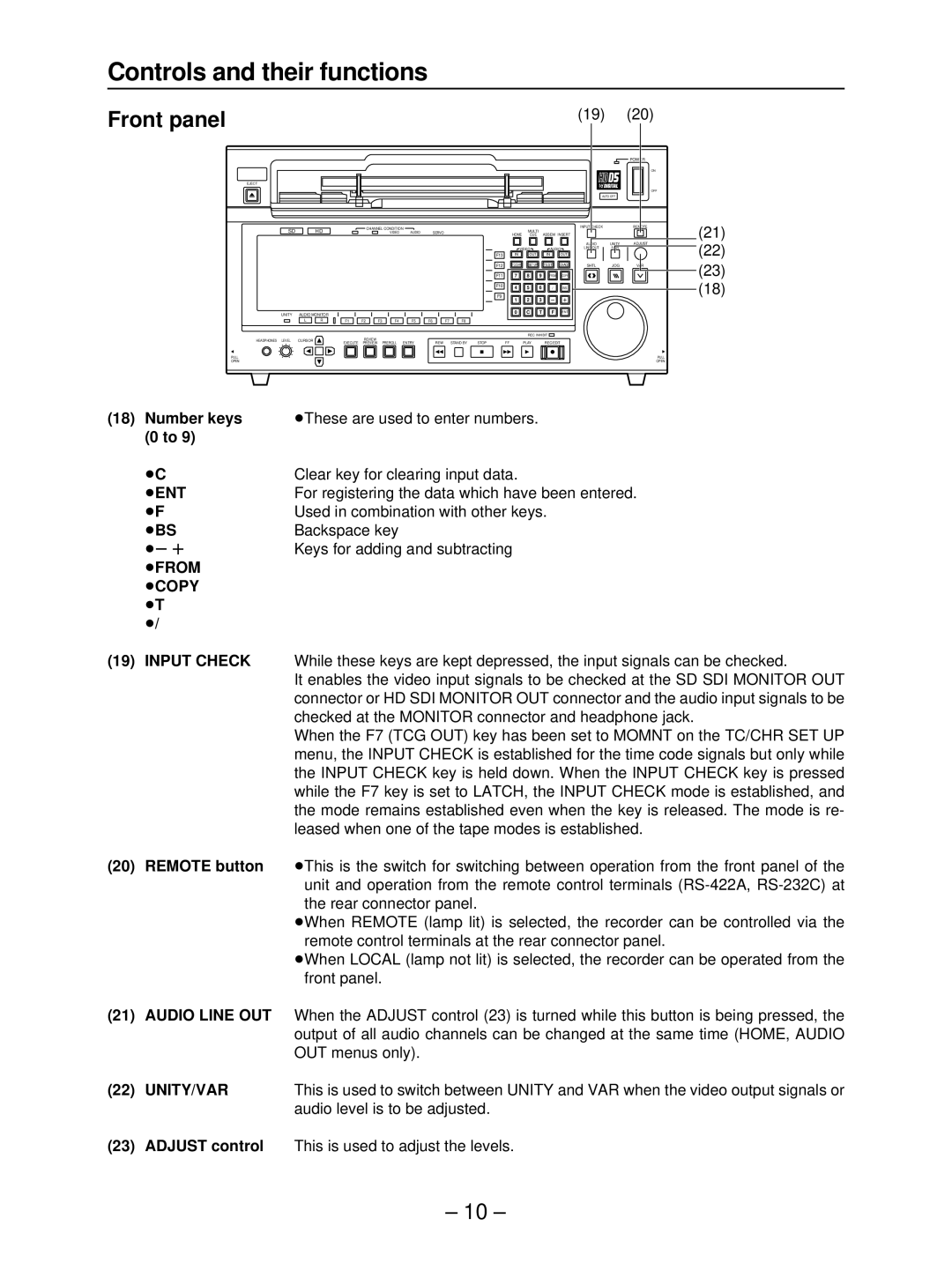
(18)Number keys ≥These are used to enter numbers.
(0 to 9)
≥C | Clear key for clearing input data. |
≥ENT | For registering the data which have been entered. |
≥F | Used in combination with other keys. |
≥BS | Backspace key |
≥s r | Keys for adding and subtracting |
≥FROM |
|
≥COPY |
|
≥T |
|
≥/ |
|
(19)INPUT CHECK While these keys are kept depressed, the input signals can be checked.
It enables the video input signals to be checked at the SD SDI MONITOR OUT connector or HD SDI MONITOR OUT connector and the audio input signals to be checked at the MONITOR connector and headphone jack.
When the F7 (TCG OUT) key has been set to MOMNT on the TC/CHR SET UP menu, the INPUT CHECK is established for the time code signals but only while the INPUT CHECK key is held down. When the INPUT CHECK key is pressed while the F7 key is set to LATCH, the INPUT CHECK mode is established, and the mode remains established even when the key is released. The mode is re- leased when one of the tape modes is established.
(20)REMOTE button ≥This is the switch for switching between operation from the front panel of the unit and operation from the remote control terminals
≥When REMOTE (lamp lit) is selected, the recorder can be controlled via the remote control terminals at the rear connector panel.
≥When LOCAL (lamp not lit) is selected, the recorder can be operated from the front panel.
(21)AUDIO LINE OUT When the ADJUST control (23) is turned while this button is being pressed, the output of all audio channels can be changed at the same time (HOME, AUDIO OUT menus only).
(22) UNITY/VAR | This is used to switch between UNITY and VAR when the video output signals or |
| audio level is to be adjusted. |
(23)ADJUST control This is used to adjust the levels.
– 10 –
