Controls and their functions
Front panel
(4) | (6) | (5) | (3) (1) (2) |
(7)
(8)
(9)
|
|
|
|
|
|
|
|
|
|
|
|
|
|
|
|
|
|
| POWER |
|
|
|
|
|
|
|
|
|
|
|
|
|
|
|
|
|
|
| ON |
EJECT |
|
|
|
|
|
|
|
|
|
|
|
|
|
|
|
|
|
|
|
|
|
|
|
|
|
|
|
|
|
|
|
|
|
|
|
|
|
| OFF |
|
|
|
|
|
|
|
|
|
|
|
|
|
|
|
|
| AUTO OFF |
| |
SD |
| HD |
| CHANNEL CONDITION |
|
|
|
|
|
|
|
|
| INPUT CHECK |
| REMOTE | |||
|
|
|
| VIDEO | AUDIO |
| SERVO |
|
| HOME | MULTI |
| ASSEM INSERT |
|
|
| |||
|
|
|
|
|
|
|
|
|
|
|
| CUE |
|
|
|
| |||
|
|
|
|
|
|
|
|
|
|
|
|
|
|
|
|
| AUDIO | UNITY | ADJUST |
|
|
|
|
|
|
|
|
|
|
|
| VIDEO |
| AUDIO | LINE OUT | /VAR |
| ||
|
|
|
|
|
|
|
|
|
|
| F13 | IN | OUT |
| IN | OUT |
|
|
|
|
|
|
|
|
|
|
|
|
|
| F12 | TC/CHR | SET UP |
| TEST | DIAG | SHTL | JOG | VAR |
|
|
|
|
|
|
|
|
|
|
| F11 | 7 | 8 | 9 | FROM | COPY |
|
|
|
|
|
|
|
|
|
|
|
|
|
| F10 | 4 | 5 | 6 | / | BS |
|
|
|
|
|
|
|
|
|
|
|
|
|
|
|
|
|
| |||||
|
|
|
|
|
|
|
|
|
|
| F9 | 1 | 2 | 3 |
|
|
|
|
|
|
|
|
|
|
|
|
|
|
|
|
|
|
|
|
|
| |||
UNITY | AUDIO MONITOR |
|
|
|
|
|
|
|
|
| 0 | C | T | F | ENT |
|
|
| |
|
|
|
|
|
|
|
|
|
|
|
|
|
|
|
|
| |||
| L | R | F1 | F2 | F3 | F4 | F5 | F6 | F7 | F8 |
|
|
|
|
|
|
|
|
|
|
|
|
|
|
|
|
|
|
|
|
|
| REC INHIBIT |
|
|
|
| ||
HEADPHONES LEVEL | CURSOR |
| EXECUTE | REVIEW |
| PREROLL | ENTRY |
| REW | STAND BY | STOP | FF | PLAY |
| REC/EDIT |
|
|
| |
|
|
| PREVIEW |
|
|
|
|
|
| ||||||||||
PULL |
|
|
|
|
|
|
|
|
|
|
|
|
|
|
|
|
|
| PULL |
OPEN |
|
|
|
|
|
|
|
|
|
|
|
|
|
|
|
|
|
| OPEN |
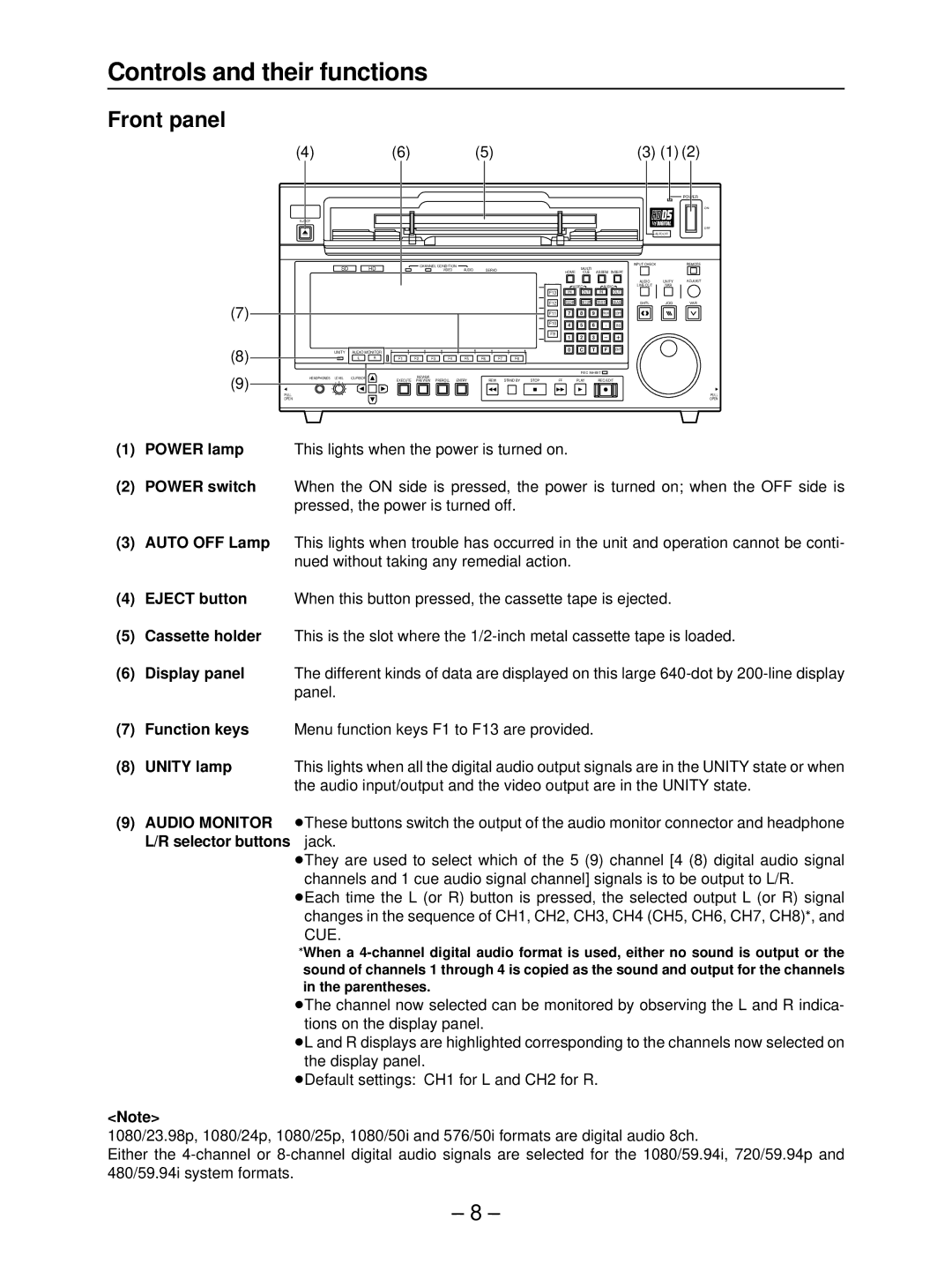
0(1) | POWER lamp | This lights when the power is turned on. |
0(2) | POWER switch | When the ON side is pressed, the power is turned on; when the OFF side is |
|
| pressed, the power is turned off. |
0(3) | AUTO OFF Lamp | This lights when trouble has occurred in the unit and operation cannot be conti- |
|
| nued without taking any remedial action. |
0(4) | EJECT button | When this button pressed, the cassette tape is ejected. |
0(5) | Cassette holder | This is the slot where the |
0(6) | Display panel | The different kinds of data are displayed on this large |
|
| panel. |
0(7) | Function keys | Menu function keys F1 to F13 are provided. |
0(8) | UNITY lamp | This lights when all the digital audio output signals are in the UNITY state or when |
|
| the audio input/output and the video output are in the UNITY state. |
0(9) | AUDIO MONITOR | ≥These buttons switch the output of the audio monitor connector and headphone |
L/R selector buttons ≥jack.
≥They are used to select which of the 5 (9) channel [4 (8) digital audio signal channels and 1 cue audio signal channel] signals is to be output to L/R.
≥Each time the L (or R) button is pressed, the selected output L (or R) signal changes in the sequence of CH1, CH2, CH3, CH4 (CH5, CH6, CH7, CH8)°, and CUE.
°When a
≥The channel now selected can be monitored by observing the L and R indica- tions on the display panel.
≥L and R displays are highlighted corresponding to the channels now selected on the display panel.
≥Default settings: CH1 for L and CH2 for R.
<Note>
1080/23.98p, 1080/24p, 1080/25p, 1080/50i and 576/50i formats are digital audio 8ch.
Either the
– 8 –
