Major operating controls and their functions
Interface bracket
ENGLISH
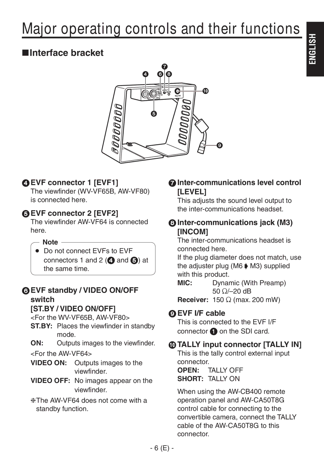
EVF connector 1 [EVF1]
The viewfinder
5EVF connector 2 [EVF2]
7
This adjusts the sound level output to the
The viewfinder | 8 | |||||
here. | [INCOM] | |||||
|
|
| The | |||
| Note | |||||
|
|
| connected here. | |||
Do not connect EVFs to EVF | ||||||
|
| connectors 1 and 2 (4 and 5) at | If the plug diameter does not match, use | |||
|
| the adjuster plug (M6 M3) supplied | ||||
|
| the same time. | ||||
|
| with this product. | ||||
|
|
|
| |||
6 EVF standby / VIDEO ON/OFF | MIC: | Dynamic (With Preamp) | ||||
| 50 | |||||
switch | Receiver: 150 (max. 200 mW) | |||||
[ST.BY / VIDEO ON/OFF] | 9 EVF I/F cable | |||||
<For the | ||||||
This is connected to the EVF I/F | ||||||
ST.BY: Places the viewfinder in standby | ||||||
connector 1 on the SDI card. | ||||||
|
| mode. | ||||
|
|
|
| |||
ON: | Outputs images to the viewfinder. | TALLY input connector [TALLY IN] | ||||
<For the | This is the tally control external input | |||||
VIDEO ON: Outputs images to the | connector. | |||||
|
|
| viewfinder. | OPEN: | TALLY OFF | |
VIDEO OFF: No images appear on the | SHORT: TALLY ON | |||||
|
|
| viewfinder. | When using the | ||
The | operation panel and | |||||
standby function. | control cable for connecting to the | |||||
|
|
|
| convertible camera, connect the TALLY | ||
|
|
|
| cable of the | ||
|
|
|
| connector. | ||
|
| - | (E) - |
| ||