■Installation
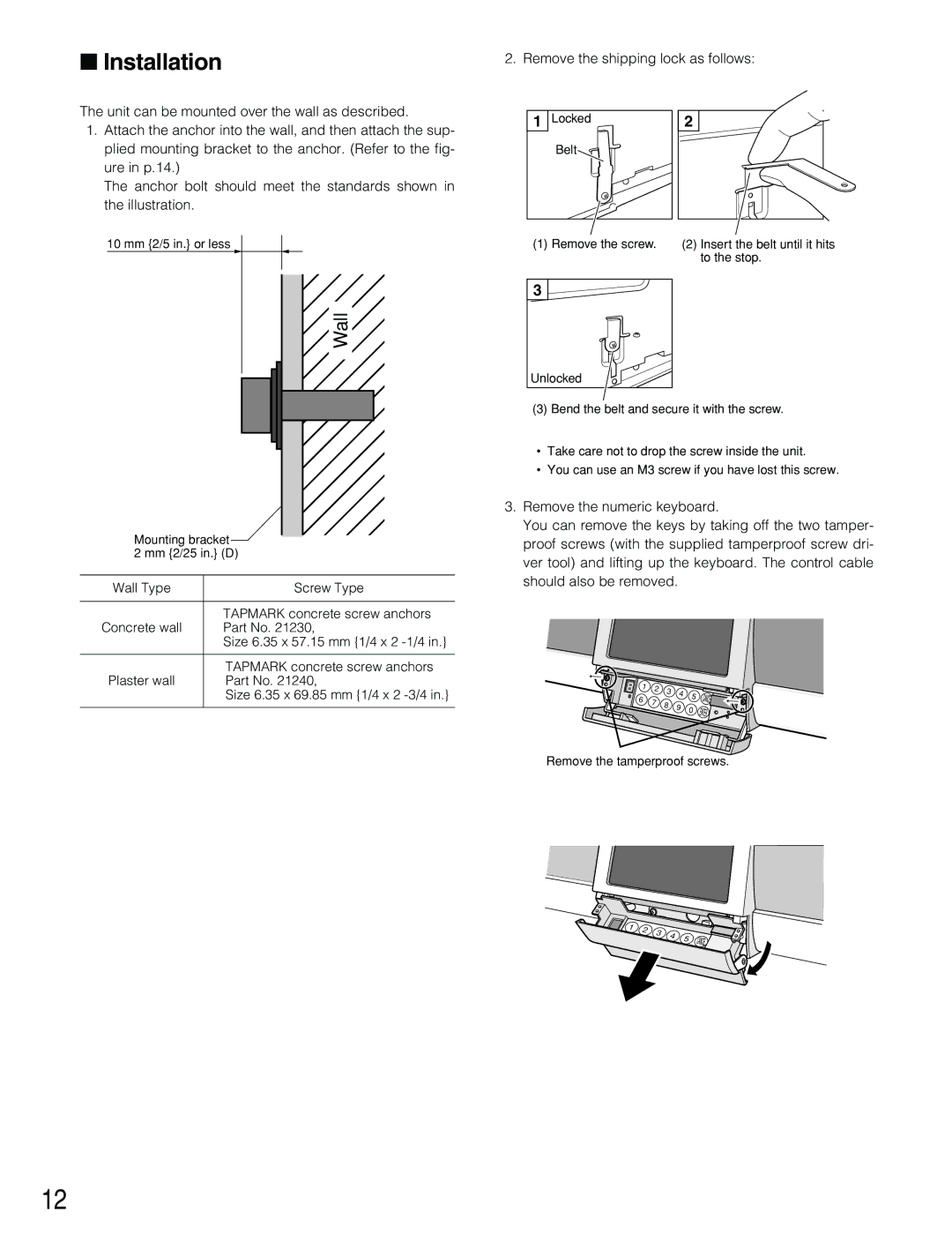
The unit can be mounted over the wall as described.
1.Attach the anchor into the wall, and then attach the sup- plied mounting bracket to the anchor. (Refer to the fig- ure in p.14.)
The anchor bolt should meet the standards shown in the illustration.
10 mm {2/5 in.} or less
Wall
Mounting bracket
2 mm {2/25 in.} (D)
Wall Type | Screw Type |
|
|
| TAPMARK concrete screw anchors |
Concrete wall | Part No. 21230, |
| Size 6.35 x 57.15 mm {1/4 x 2 |
|
|
| TAPMARK concrete screw anchors |
Plaster wall | Part No. 21240, |
| Size 6.35 x 69.85 mm {1/4 x 2 |
|
|
2. Remove the shipping lock as follows:
1 | Locked | 2 |
| Belt |
|
(1) Remove the screw. | (2) Insert the belt until it hits |
| to the stop. |
3 |
Unlocked |
(3) Bend the belt and secure it with the screw.
•Take care not to drop the screw inside the unit.
•You can use an M3 screw if you have lost this screw.
3.Remove the numeric keyboard.
You can remove the keys by taking off the two tamper- proof screws (with the supplied tamperproof screw dri- ver tool) and lifting up the keyboard. The control cable should also be removed.
1 | 2 | 3 | 4 |
|
| |
| 5 | CANCEL | ||||
6 |
| |||||
7 |
| |||||
8 |
| |||||
9 | 0 | |||||
| ENTER | |||||
|
| |||||
|
|
| ||||
|
|
|
| |||
|
|
|
|
|
Remove the tamperproof screws.
1 | 2 | 3 | 4 |
|
|
| 5 | ||
|
|
| ||
|
|
|
|
CANCEL
12