Manuals
/
Panasonic
/
Household Appliance
/
Air Conditioner
Panasonic
CU-5E36QBU
service manual
Electronic Circuit Diagram
Models:
CU-5E36QBU
1
13
71
71
Download
71 pages
27.09 Kb
10
11
12
13
14
15
16
17
Troubleshooting
Specs
Operation Characteristics
Install
Refrigeration Cycle Diagram
Wiring
Dimension
Outdoor Unit Removal Procedure
Safety Precautions
Cooling Powerful Operation
Page 13
Image 13
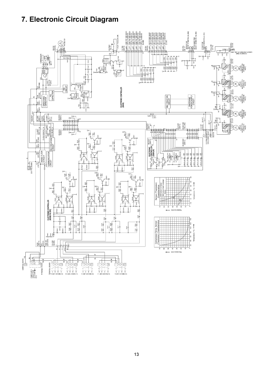
7. Electronic Circuit Diagram
13
Page 12
Page 14
Page 13
Image 13
Page 12
Page 14
Contents
Destination Canada
Air Conditioner Outdoor Unit
Table of Contents
Safety Precautions
Page
Outdoor Unit
Specifications
Outdoor Unit
∙ Multi Split Combination Possibility
Room Indoor Unit Capacity Total Indoor
Dimensions
Refrigeration Cycle Diagram
Block Diagram
Electronic Controller Noise Filter
Wiring
Electronic Circuit Diagram
Main Printed Circuit Board
Printed Circuit Board
Page
Check Points
Installation Information
Select The Best Location
Installation Instruction
Connect The Piping
Install The Outdoor Unit
Cutting and Flaring the Piping
Evacuation Of The Equipment
Heat Insulation
Connect The Cable To The Outdoor Unit
Disposal Of Outdoor Unit Drain Water
Operation Control
Cooling Powerful Operation
Cooling Operation
Outdoor fan control
Heating Operation
Powerful Operation
Heating Room Temp Sampling Control
Simultaneous Operation Control
Electronic Parts Temperature Rise Protection 2 Cool
Electronic Parts Temperature Rise Protection 1 Cool
Protection Control
Freeze Prevention control Cool
Heating overload control Heat
Cooling overload control Cool
IPM power transistor Protection Control
Time Delay Safety Control Restart Control
Deice Control
13.10 30 seconds Force Operation
Valve close detection control
Compressor Protection Control Gas leak detection control
Compressor discharge high pressure protection control
Pump down operation SW1
Servicing Mode
Test Run Operation
Power Save Mode
Wiring Error Check
Mode priority function
Cooling only function
Self Diagnosis Function
Troubleshooting Guide
Page
Page
Outdoor Unit Removal Procedure
Disassembly and Assembly Instructions
Removing the Cabinet Top Plate
Remove the Control Board Cover and Particular Plates
Removing the Cabinet Front Plate
Removing the Propeller Fan and Fan Motor
Removing the Control P.C. Board
Operation Characteristics
Technical Data
One Indoor Unit Operation
Page
Page
Page
Page
Page
Page
Page
Two Indoor Unit Operation
Page
Page
Page
Page
Page
Page
Page
Page
Page
Page
Page
Three Indoor Unit Operation
Page
Page
Page
Page
Page
Page
Page
Four Indoor Unit Operation
Page
Five Indoor Unit Operation
Page
Exploded View and Replacement Parts List
Safety REF.NO Description & Name QTY CU-5E36QBU Remark
Installation Instruction
Top
Page
Image
Contents