
CS-E9NKUAW, CU-E9NKUA, CU-E12NKUA, CS-E12NKUAW specifications
Panasonic has established itself as a leader in the air conditioning market, offering a range of products that combine advanced technology with energy efficiency. The Panasonic models CS-E12NKUAW, CU-E12NKUA, CU-E9NKUA, CSU-2E18NBU, and CS-E9NKUAW exemplify this commitment to quality and innovation.The CS-E12NKUAW and CS-E9NKUAW are split-type air conditioners designed for residential use. One of the standout features of these models is their energy-efficient inverter technology. This innovation allows the compressor to adjust its speed according to the cooling demand, leading to lower energy consumption and cost savings for homeowners. Additionally, these units operate quietly, ensuring a peaceful environment while effectively maintaining comfortable temperatures.
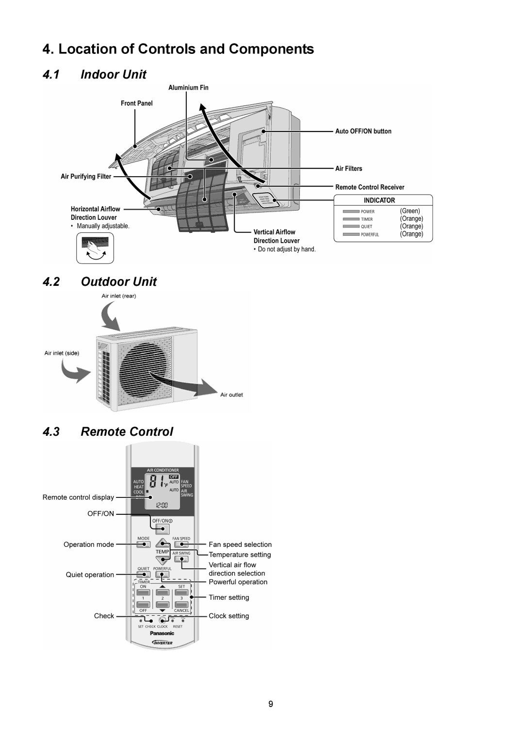
The CU-E12NKUA and CU-E9NKUA are the corresponding outdoor units that support the indoor models. These units are designed for durability and performance, using robust materials that withstand various weather conditions. Panasonic's outdoor units are equipped with a reliable cooling system that enhances the overall efficiency and longevity of the air conditioning system.
The CSU-2E18NBU model is perfect for larger spaces, handling greater loads while ensuring consistent cooling. This unit also leverages inverter technology for efficient operation. The CSU models often include advanced features such as a high-density filter that captures dust and allergens, promoting a healthier indoor environment.
All these units are designed with user-friendly interfaces, allowing for easy temperature control and adjustments. Many of the models also come with remote control options, enabling users to regulate their comfort from the convenience of their seat. Additionally, advanced air purifying technology enhances indoor air quality by eliminating harmful pollutants and odors.
Panasonic air conditioners are known for their environmentally friendly refrigerants, contributing to a reduced carbon footprint and compliance with international standards. These features reflect Panasonic's commitment to sustainability and innovation, making these models a leading choice for consumers looking to balance comfort, efficiency, and environmental responsibility.
In summary, Panasonic's CS-E12NKUAW, CU-E12NKUA, CU-E9NKUA, CSU-2E18NBU, and CS-E9NKUAW models represent some of the best in today's air conditioning market, with key features including energy efficiency, user-friendly controls, advanced air purification, and robust outdoor units designed for performance and reliability. These units provide an ideal solution for maintaining a comfortable home environment while being conscious of energy use and environmental impact.